background image

5 - 1

5 - 1

CIRCUIT DIAGRAM - MAIN BOARD

PART 1

CD DOOR SWITCH BD.

OPEN

CLOSE

GND

CLOSE

DGND

OPEN

M-

M+

O

U

T2

P

2

V

C

C

2

V

C

C

1

IN

2

IN

1

V

Z

P

1

O

U

T1

G

N

D

DGND

TO

 S

W

TO

 C

N

40

5

TO

 MO

TA

GND

GND

GND

GND

GND

GND

GND

VC25

VC25

CLOSE-DET

CLOSE-DET

CD_RX

IR

VFD-CS

VFD-CS

CD_TX

PCF8563_SCL

PCF8563_SCL

AUDIO_IN_1

AUDIO_IN_1

PCF8563_DATA

PCF8563_DATA

EQ-SCL

PC_RST

P-CD

IIC-SDA

IIC-SDA

EQ-SDA

IIC-SCL

IIC-SCL

KEY1

IRQ

IRQ

CDPWR

VFD-WR

VFD-WR

PLL_CS

VFD-DAT

VFD-DAT

AUDIO_IN_2

AUDIO_IN_2

LOV-TADA

MCU-MUTE

ST-BY

IO

D

E

T1

3

VOL-CLK

DET30

RX

TX

P_CON

+12VCC

MCU3.3V

3.3VIO

3.3VIO

3.

3V

IO

3.3VIO

3.3VIO

3.3VIO

3.3VIO

EQ_LOUT

EQ_ROUT

R724

R_0B

330R

1

2

1

2

GND   14

GND   11

SDA  1 3

SCL  1 2

4 VCC

5 VDD

IC7 05

\MYSON\MYSON MCU\CM5228_CS8958\MULTI-SINGLEWRITER\CS8953 DB CB\MSW_SB_CM5245.DSN

MF1341S 2161

1

2

3

4

5

6

7

8

9

10

11

12

13

14

15

16

17

18

19

20

R722

R_0B

33OR

1

2

1

2

R71 9

R_0B

1K

1

2

1

2

R720

R_0B

33OR

1

2

1

2

R78 3

R_0B

1K

1

2

1

2

C73 0

CA

100 P

1

2

1

2

C455

0.1UF

C73 1

CA

100 P

1

2

1

2

R70 7

RA

1K

1

2

2

1

C73 2

CA

100 P

1

2

1

2

R763 A

RESISTOR

10K

1

2

1

2

R70 6

R_0A

1K

1

2

1

2

R762 A

RESISTOR

10K

1

2

1

2

R70 8

R_0A

1K

1

2

1

2

D407

0R

R11 1

R_0A

1K

1

2

1

2

D408

0R

R71 8

RA

1K

1

2

1

2

Q40 9

NPN_2

NC

1

2

3

1

2

3

R70 9

R_0A

1K

1

2

1

2

R31 0

RB

NC

1

2

2

1

R73 7

R_0B

1K

1

2

2

1

R

76

4

RESISTOR

10

K

1

2

1

2

R71 7

R_0B

8.2K

1

2

2

1

R

70

4

RA

10

K

1

2

1

2

SW2701A

C

72

4

0.

01

U

F

IC304

LB1641

1

2

3

4

5

6

7

8

9

10

C

72

5

0.

01

U

F

C302

0.1UF

R82

R_0B

1K

1

2

1

2

ZD304

5.6V

R83

R_0B

1K

1

2

1

2

C386

220uF/16V

R84

R_0B

330 R

1

2

1

2

C339

0.1UF

R85

R_0B

330 R

1

2

1

2

C336 0.1UF

BC9

CAP_NPA

0.1uF

1

2

1

2

C

33

3

0.

01

U

F

X2

CRYSTALB

32.768KH z

1

2

2

1

C397 0.1UF

R86

RF

10K

1

2

2

1

L304

10uH

C78

CAPACITOR_NON-POLB

82p F

1

2

1

2

R30 2

RB

2.2 1/2W

1

2

2

1

+

C79

CAPACITOR_POLB

100uF/1 0V

1

2

1

2

R30 8

RB

10K

1

2

2

1

1 O

I

2 O

O

3 IN

T1

4 V

SS

VD

D 8

CO

UT

 7

SC

L 6

SD

A 5

U6

HV826MG_0

PCF8563

1

2

3

4

5

6

7

8

OI

OO

INT1

VSS

SDA

SCL

COUT

VDD

R30 9

RB

10K

1

2

2

1

R

87

RESISTOR

10

K

1

2

1

2

R72 3

R_0B

330

1

2

1

2

R

88

RESISTOR

10

K

1

2

1

2

R72 1

R_0B

1K

1

2

1

2

Q702 A1

NPN_2

805 0

1

2

3

1

2

3

R726

R_0B

33OR

1

2

1

2

R89

RA

300 K

1

2

1

2

R728

R_0B

330R

1

2

1

2

C80

CA

105

1

2

1

2

R766

R_0B

0

1

2

2

1

R90

RA

100 K

1

2

1

2

D705

1N4148

R92

RF

10K

1

2

2

1

R99 5

RESISTOR

10K

1

2

1

2

C81

CAPACITOR_NON-POLB

103

1

2

1

2

R99 6

RESISTOR

10K

1

2

1

2

R93

RA

100 R

1

2

1

2

R11 7

RESISTOR

10K

1

2

1

2

Q702 A2

NPN_2

805 0

1

2

3

1

2

3

C

N

40

4

1

2

R94

RA

300 K

1

2

1

2

C

N

70

4

1

2

3

4

C82

CA

105

1

2

1

2

R72 5

R_0B

1K

1

2

1

2

SW2701B

R95

RA

100 K

1

2

1

2

+

TC70 2

CAPACITOR_POL

4.7UF

1

2

1

2

C

N

40

5

1

2

3

4

R96

RF

10K

1

2

2

1

+

TC70 5

CAPACITOR_POL

4.7UF

1

2

1

2

R29

R_0B

330 R

1

2

1

2

C83

CAPACITOR_NON-POLB

103

1

2

1

2

1 GND

2 GND

3 GND

7 WP

4 G

ND

SDA 5

SCL 6

VC

C

U1

AT24C01A_P_0

AT24C02S MT

1

2

3

4

5

6

7

8

A0

A1

A2

G

N

D

SDA

SCL

WP

V

C

C

R73 9

R_0B

1K

1

2

1

2

R97

RA

100 R

1

2

1

2

R71 0

RA

100 K

1

2

2

1

R771

R_0B

1K

1

2

1

2

R78 2

RA

1K

1

2

1

2

R71 5

R_0B

10K

1

2

1

2

C70 1

CAP_NP

0.1uF

1

2

1

2

R71 3

RA

10K

1

2

1

2

C70 2

CAP_NP

0.1uF

1

2

1

2

Q702 A

NPN_2

805 0

1

2

3

1

2

3

P2_6/T1/CMPB 25

P2_5/T2/CMPC 26

P2_4/T2EX/CMPD 27

P2_3/RXD1 28

P2_2/TXD1 29

P2_1/XOUT 30

VSS 32

P2_0/XIN 31

P

1_

7/P

IN

TO

_1 1

P

1_

6/P

IN

TO

_0 2

P

1_

3/S

C

L  3

P

1_

2/S

D

A  4

P

3_

1  5

P

3_

0  6

P

1_

5/R

XO

UT

  7

P

1_

4/R

XIN

  8

P1_1/ADD4   9

P1_0/ADD3   10

P0_7/RXDO/ADD2   11

P0_6/TXDO/ADD1  12

P0_5/TPINT1_5/ADC   13

P0_4/TPINT1_4/ADC   14

P0_3/TPINT1_3/ADB  15

P0_2/TPINT1_2/ADB  16

P

0_

1/

/A

D

A2

  1

7

P

0_

0/

/A

D

A1

  1

8

V

D

D

25

  1

9

V

D

D

  2

0

R

S

T

N

  2

1

P

3_

 2

2

P

3_

 2

3

P2

_7

/T

O

/C

M

PA

  2

4

U702

MTV212_0

CA68 12

\MYSON\MYSON MCU\CM5228_CS8958\MULTI-SINGLEWRITER\CS8953 DB CB\MSW_SB_CM5245.DSN

1

2

3

4

5

6

7

8

9

10

11

12

13

14

15

16

17

18

19

20

21

22

23

24

25

26

27

28

29

30

31

32

P

1_

7/

P

IN

T0

_1

P

1_

6/

P

IN

T0

_0

P

1_

3/

S

C

L

P

1_

2/

S

D

A

P

3_

1

P

3_

0

P

1_

5/

R

X

O

U

T

P

1_

4/

R

X

IN

P1_1/ADD4

P1_0/ADD3

P0_7/RXD0/ADD2

P0_6/TXD0/ADD1

P0_5/PINT1_5/ADC

P0_4/PINT1_4/ADC

P0_3/PINT1_3/ADB

P0_2/PINT1_2/ADB

P

0_

1/

/A

D

A

2

P

0_

0/

/A

D

A

1

V

D

D

25

V

D

D

R

S

TN

P

3_

3

P

3_

2

P

2_

7/

T0

/C

M

P

A

P2_6/T1/CMPB

P2_5/T2/CMPC

P2_4/T2EX/CMPD

P2_3/RXD1

P2_2/TXD1

P2_1/XOUT

P2_0/XIN

VSS

+

TC70 3

CAPACITOR_POL

NC

1

2

1

2

C6

CAP_NP

0.1uF

1

2

1

2

R70 3

RA

10K

1

2

1

2

R77 0

R_0B

330

1

2

1

2

+

C31 8

CAPACITOR_POL

100U F

1

2

1

2

R76 9

R_0B

330

1

2

1

2

R75 0

R_0B

330

1

2

1

2

R75 1

RESISTOR

3.3K

1

2

1

2

R75 9

R_0B

330

1

2

1

2

R75 5

RESISTOR

3.3K

1

2

1

2

C70 8

CA

1000 PF

1

2

1

2

Summary of Contents for MCM3000

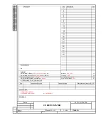
Page 1: ...ronic mechanical photocopying or otherwise without the prior permission of Philips CONTENTS Technical specification and version variation 1 Service measurement setup 1 3 Service aids 1 4 Instructions on CD playability 2 1 2 2 Block diagram 3 1 Wiring diagram 4 1 Disassembly diagram 4 2 4 3 Main board Circuit diagra 5 1 5 4 Layout diagram 5 5 CD board Circuit diagram 6 1 Layout diagram 6 2 DISPLAY ...

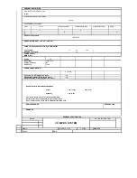
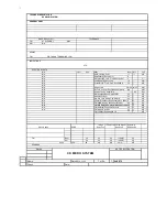
Page 2: ...EMOTE CONTROL NA CABINET 41 Dimensions with Boxes L XXX x W XXX x H XXX mm Material XXX XXX 38 Dimensions without Boxes XXX XXX XXX mm LxWxH Finishing XXX 39 Weight including packing XXX kg Unit in Mastercarton N A 40 Weight excluding packing and batteries XXXkg Units in Dealercarton 1 set Pos Connection Function Connector type Electrical data input or R O P INTERCONNECTION POSSIBILITIES SET SPECI...

Page 3: ...peration 1 8 Prated Nom AC input 50W Standby Demo Mode Off Nom AC input 3W ECO Standby No FTD Display Nom AC input 1W Q and R according to Product Division Rules Loudspeaker Boxes CD PLAYER W PLL RADIO AUX 2X60W Q and R according to Product Division Rules Quality 0 4 major 1 5 minor Reliability 2 0 C42 Tested according to General Test Instruction UAN D1591 Measured According to UAN L1059 unless ot...

Page 4: ...e 500mV to AUX in socket with frequencies indicated in Table 1 Table 1 Tolerance 3dB DIGITAL SOUND CONTROL DSC FREQUENCY RESPONSE dB 10KHz 5 3 1 0 3 15 3 1 5 3 15 3 2 5 3 5 3 3 2 MAX 0 3 Flat Jazz 100Hz 5 2 2 2 3 2 1K 1 1 0 1K 0 10K 0 100 3 2 100 0 Loudness dB VOL STEP DSC Frequency Hz Response dB DBB dB 100Hz SUPPLY AF AMPLIFIER LOUDSPEAKER BOX SPECIFICATION Pops Rock Classic 10K 0 1 10K 4 1 100 ...

Page 5: ... signal to noise ratio 65 dBA Shock sens 3g OUTPUT POWER 4 ohm Loading Mains Operation 2 X 60W NORMAL Frequency Response 100Hz 16KHz within 3 3dB REF output ipod iphone Compatibility iPod 5G iPod nano 1G 2G 3G Classic iPod Touch iPhone included 3GS Iphone4 Ipad ipod iphone charging 2100mA 2 X 55W LIMIT 2 5 mW 2 dB R Load 32 ohm max At cold condition with 10 THD 1KHz Euro Nafta CD DA CD R RW MP3 0d...

Page 6: ...ity 60 Sec N A AM Suppression I P 48 82dBf 30 25 dB N A Modulation Hum 55 45 dB N A 8th 9th 10th Harmonics Whistle 40 35 dB N A Overall Frequency Response 63 12 5kHz 0 3 dB N A FM 46dB Quiying sensitivity Stereo 45 50 dbf N A FM S N Ratio A weighted Mono input 68d 55 50 dB N A FM S N Ratio A weighted Mono input 68d 55 50 N A FM Adjacent Channel selectivity 20 25 dB N A FM Image Rejection 30 20 dB ...

Page 7: ...er 3 32kHz 44 1KHZ 48kHz Joliet 8 character OSD display Windows XP UDF basic close format Mp3 multisession Directory resting Max 8 level Max directory 32 Display filename ID3 255 folders 999songs ipod iphone performance description Channel balance Limit 2dB singnal to noise ratio unweighted Limit 60dB Channel seperation Limit 45dB Max volume noise Bass off Limit 3mV Max volume noise Bass off Limit...

Page 8: ...ource Remarks Time Setting 24 Hrs Wake Up Volume Control No Volume at Wakeup NC No of Timer Settings 1 Clock Accuracy Lim 2 sec day RC operating distance INDICATORS Display Type VFD REMARKS VERSION OVERVIEW Tape PART SPECIFICATION Name Date 2010 11 15 Tot Sh Check Date 7 SHEET 7 Revise CD MICRO SYSTEM SET SPECIFICATION ...

Page 9: ...15kHz e g 7122 707 48001 LF Voltmeter e g PM2534 DUT S N and distortion meter e g Sound Technology ST1700B Frame aerial e g 7122 707 89001 Tuner AM MW LW To avoid atmospheric interference all AM measurements have to be carried out in a Faraday s cage Use a bandpass filter or at least a high pass filter with 250Hz to eliminate hum 50Hz 100Hz RF Generator e g PM5326 Ri 50 Bandpass 250Hz 15kHz e g 71...

Page 10: ...ng make sure that you are connected with the same potential as the mass of the set via a wrist wrap with resistance Keep components and tools also at this potential ESD CLASS 1 LASER PRODUCT GB Safety regulations require that the set be restored to its original condition and that parts which are identical with those specified be used Safety components are marked by the symbol Lead free ...

Page 11: ...T OK check playability N Y playability ok check playability check playability return set Customer complaint CD related problem fast lens cleaning 1 2 3 For flap loaders access to CD drive possible cleaning method 4 is recommended INSTRUCTIONS ON CD PLAYABILITY 2 1 Exchange CDM 1 4 For description see following pages ...

Page 12: ...viously caused by a scratched dirty or copy protected CD In case problems remain the customer is requested to contact the workshop directly The lens cleaning method 3 should be mentioned in the addendum sheet The final wording in national language as well as the printing is under responsibility of the Regional Service Organizations 4 LIQUID LENS CLEANING Because the material of the lens is synthet...

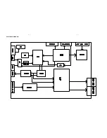
Page 13: ...SET BLOCK DIAGRAM 3 1 3 1 ...

Page 14: ...SET WIRING DIAGRAM 4 1 4 1 ...

Page 15: ...8050 1 2 3 1 2 3 R726 R _ 0 B 33OR 1 2 1 2 R89 RA 300K 1 2 1 2 R728 R _ 0 B 330R 1 2 1 2 C80 C A 105 1 2 1 2 R766 R _ 0 B 0 1 2 2 1 R90 RA 100K 1 2 1 2 D705 1N4148 R92 RF 10K 1 2 2 1 R995 R E S I S T O R 10K 1 2 1 2 C81 CAPACITOR_NON POLB 103 1 2 1 2 R996 R E S I S T O R 10K 1 2 1 2 R93 RA 100R 1 2 1 2 R117 R E S I S T O R 10K 1 2 1 2 Q702 A2 NPN_2 8050 1 2 3 1 2 3 CN404 1 2 R94 RA 300K 1 2 1 2 CN...

Page 16: ...K C70 100PF C71 100PF CN606 3P 2 0mm 1 2 3 JK603 AUX JACK 1 2 3 L7 R B FB300 1 2 2 1 L8 R B FB300 1 2 2 1 C37 100uF 16V LED701 LED STANDBY 1 2 E D O H T A C E D O N A C38 0 1u R752 R B 2 2K 1 2 2 1 R43 10K Q704 NPN_2 9014 1 2 3 1 2 3 C39 2 2uF R758 R B 4 7K 1 2 2 1 R44 10K R789 RB 1 5K 1 2 1 2 R45 10K 1 YO 2 Y2 3 YCOM 4 Y3 5 Y1 6 INHIBIT 7 VEE 8 VSS VDD 16 X2 15 X1 14 XCOM 13 XO 12 X3 11 A 10 B 9 ...

Page 17: ...526 0 1UF L1 FB300 R424 10K R14 2K ZD201 5 6V R517 5 6K C23 47uF 10V C421 0 1UF R15 2K R211 47 C505 0 1UF C24 0 1UF C420 470uF 25V C3 100P Q408 8550 C422 0 1UF C25 470uF 25V L401 33HU 3A 1 2 C563 10uF 10V R512 5 6K 1 OUT 2 GND IN 3 IC1 HT7533 3V3 1 2 3 OUT GND IN C26 0 1UF C419 470uF 25V J4 CON10 CON10 1 2 3 4 5 6 7 8 9 10 1 2 3 4 5 6 7 8 9 10 R459 1K C404 0 0027UF C516 1UF 1 OUT 2 GND IN 3 IC2 HT...

Page 18: ...DDP2 VSSD C383 0 1u C51 0 01u C343 220p C381 0 1u C52 0 1u C327 220p C319 0 1u C450 4700uF 35V C328 220p C32 0 001u C459 0 01u R315 10 C385 0 001u L410 L 1 2 3 4 L310 33uH C320 0 001u C347 0 015 C33 100uF 35V C27 0 47u M C355 0 22u C331 0 1u M C388 0 22u C357 NC C390 0 1u R306 22 1206 C309 1000uF 35V C28 220p C360 0 1u C334 220p C393 0 1u R317 10 C394 0 1u L309 33uH C395 0 001u C304 0 47u M C396 0...

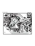
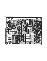
Page 19: ...LAYOUT DIAGRAM MAIN BOARD 5 5 5 5 ...

Page 20: ...SFLASH1 SFLASH 1 2 3 4 5 6 7 8 CS DO WP GND DI CLK HOLD VCC R985 R G 39K 1 2 2 1 BC904 CAPACITOR_NON POL 0 1uF 0603 1 2 1 2 R943 R G 10K 0603 1 2 2 1 2 TP1 3 TP2 IC920 ALIM5673_1 ALi M5673 1 2 3 4 5 6 7 8 9 10 11 12 13 14 15 16 17 18 19 20 21 22 23 24 25 26 27 28 29 30 31 32 33 34 35 36 37 38 39 40 41 42 43 44 45 46 47 48 49 50 51 52 53 54 55 56 57 58 59 60 61 62 63 64 65 66 67 68 69 70 71 72 73 7...

Page 21: ...LAYOUT DIAGRAM CD BOARD 6 2 6 2 ...

Page 22: ...13 14 15 16 17 18 19 20 21 22 23 24 25 26 27 28 29 30 31 32 33 34 35 36 F1 F2 NC P16 P15 P14 P13 P12 P11 P10 P9 P8 P7 P6 P5 P4 P3 P2 P1 NC NC 12G 11G 10G 9G 8G 7G 6G 5G 4G 3G 2G 1G NC F3 F4 SW2 OPEN R101 1K Q406A 8550 OSC VSS LED1 LED2 LED3 LED4 LED5 VDD G1 G2 G3 G4 G5 G6 G7 G8 S20 S19 VEE VDD S18 S17 S16 S15 S14 S13 S K12 S K11 S K10 S K9 S K8 S K7 S K6 S K5 S K4 S K3 S K2 S K1 VDD KEY4 KEY3 SW4 ...

Page 23: ...LAYOUT DIAGRAM DISPLAY KEY JACK USB BOARD TOP SIDE 7 2 7 2 ...

Page 24: ...LAYOUT DIAGRAM DISPLAY KEY JACK USB BOARD BOTTOM 7 3 7 3 ...

Page 25: ...PF D10 1N4148 R41 10K R31 NC EC15 220uF 16V R62 2 2R D6 1N4148 R32 1K C30 1UF EC13 220uF 16V R43 2 2 ZD2 NC C29 0 1UF R13 10K C15 222M 1KV R79 1R 2W C290 NC R60 10K ZD3 P6KE200 CY7 470PF 400V R73 NC R59 1 2R 2W EC5 2200uF 16V CY1 470PF 400V C31 104PF R76 22 D5 MBR10200 CY6 470PF 400V U5 TL431 R70 NC EC4 2200uF 16V C2 222M 1KV R66 470 Q6 3904 L1 5UH RV1 10241 A K R67 1K Q5 3906 B E C R25 22 R38 680...

Page 26: ...LAYOUT DIAGRAM SMPS POWER BOARD 8 2 8 2 ...

Page 27: ...EXPLODED VIEW DIAGRAM 9 1 9 1 ...

Reviews: