

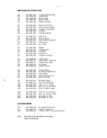
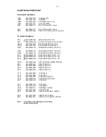

ELECTRICAL PARTSLIST
POWER BOARD ASSEMBLY
F
994000000245
BAND PASS FILTER
L14
996510023922
CHIP FERRITE BEAD 1800 +-25%
L15
996510023922
CHIP FERRITE BEAD 1800 +-25%
L16
996510023922
CHIP FERRITE BEAD 1800 +-25%
L17
996510023922
CHIP FERRITE BEAD 1800 +-25%
L901
996510023922
CHIP FERRITE BEAD 1800 +-25%
Q902
996510023918
SMD TRANSISTORS AOD413
Q904
996510023918
SMD TRANSISTORS AOD413
U1
996510019882
IC D4558
U101
996510023928
IC SI4703-C19-GM
U2
996510023941
IC TL072 (S08) SMD LOW NOISE
U200
996510012038
IC TDA8932BT
U201
996510012038
IC TDA8932BT
U202
996500039806
IC ET2314 (SOP28)
U206
994000001201
IC NJM4556AM
U59
996510012555
IC 74HC4052D
U62
996510019882
IC D4558
U901
996510023943
IC AP1509SL (SOP-8)
U902
996510023949
IC LM1117S- 5V SOT-223
X101
996500042441
X'TAL 32.768KHZ -20PPM
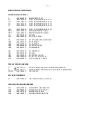
DISPLAY BOARD ASSEMBLY
T1
! 9965100
23899
TRANSFORMER(only for bare PCB:48-04MM33000320)
VFD401
996510023915
VFD DISPLAY
KEY BOARD ASSEMBLY
D1
996510023952
LED LAMP (BLUE) 2x1.75x0.74mm
USB & SD CARD BOARD ASSEMBLY
J101
996510023909
USB SOCKET (USB-4PW) 90C
J108
994000004369
PHONE JACK TC38-063-05-0
J206
996510012048
PHONE JACK D3.6mm
J403
996510023914
SD CARD 7SDCN-X0-X101-E
12 - 1
T1
! 9965100
35474
TRANSFORMER H00601A(only for bare PCB:48-04MM33000321)
Summary of Contents for MCM330
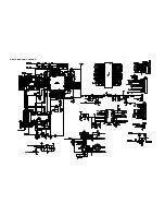
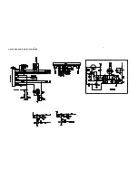
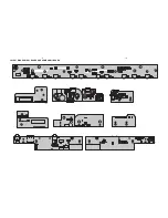
Page 10: ...CIRCUIT DIAGRAM POWER BOARD PART1 6 1 6 1 ...
Page 11: ...CIRCUIT DIAGRAM POWER BOARD PART2 6 2 6 2 ...
Page 12: ...CIRCUIT DIAGRAM POWER BOARD PART3 6 3 6 3 ...
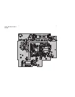
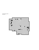
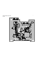
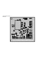
Page 13: ...LAYOUT DIAGRAM POWER BOARD TOP SIDE 6 4 6 4 ...
Page 14: ...LAYOUT DIAGRAM POWER BOARD BOTTOM SIDE 6 5 6 5 ...
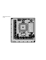
Page 15: ...CIRCUIT DIAGRAM CD BOARD 7 1 7 1 ...
Page 16: ...LAYOUT DIAGRAM CD BOARD TOP SIDE 7 2 7 2 ...
Page 17: ...LAYOUT DIAGRAM CD BOARD BOTTOM SIDE 7 3 7 3 ...
Page 18: ...CIRCUIT DIAGRAM DISPLAY VFD BOARD 8 1 8 1 ...
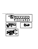
Page 19: ...LAYOUT DIAGRAM DISPLAY BOARD TOP SIDE 8 2 8 2 ...
Page 20: ...LAYOUT DIAGRAM DISPLAY BOARD BOTTOM SIDE 8 3 8 3 ...
Page 21: ...CIRCUIT DIAGRAM MCU BOARD 9 1 9 1 ...
Page 22: ...LAYOUT DIAGRAM MCU BOARD TOP SIDE 9 2 9 2 ...
Page 23: ...LAYOUT DIAGRAM MCU BOARD BOTTOM SIDE 9 3 9 3 ...
Page 25: ...LAYOUT DIAGRAM KAY BOARD AND SOME SMALL BOARD 10 2 10 2 ...