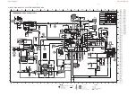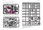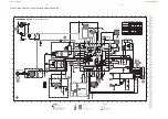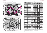
5 - 1
5 - 1
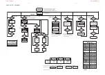
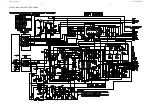
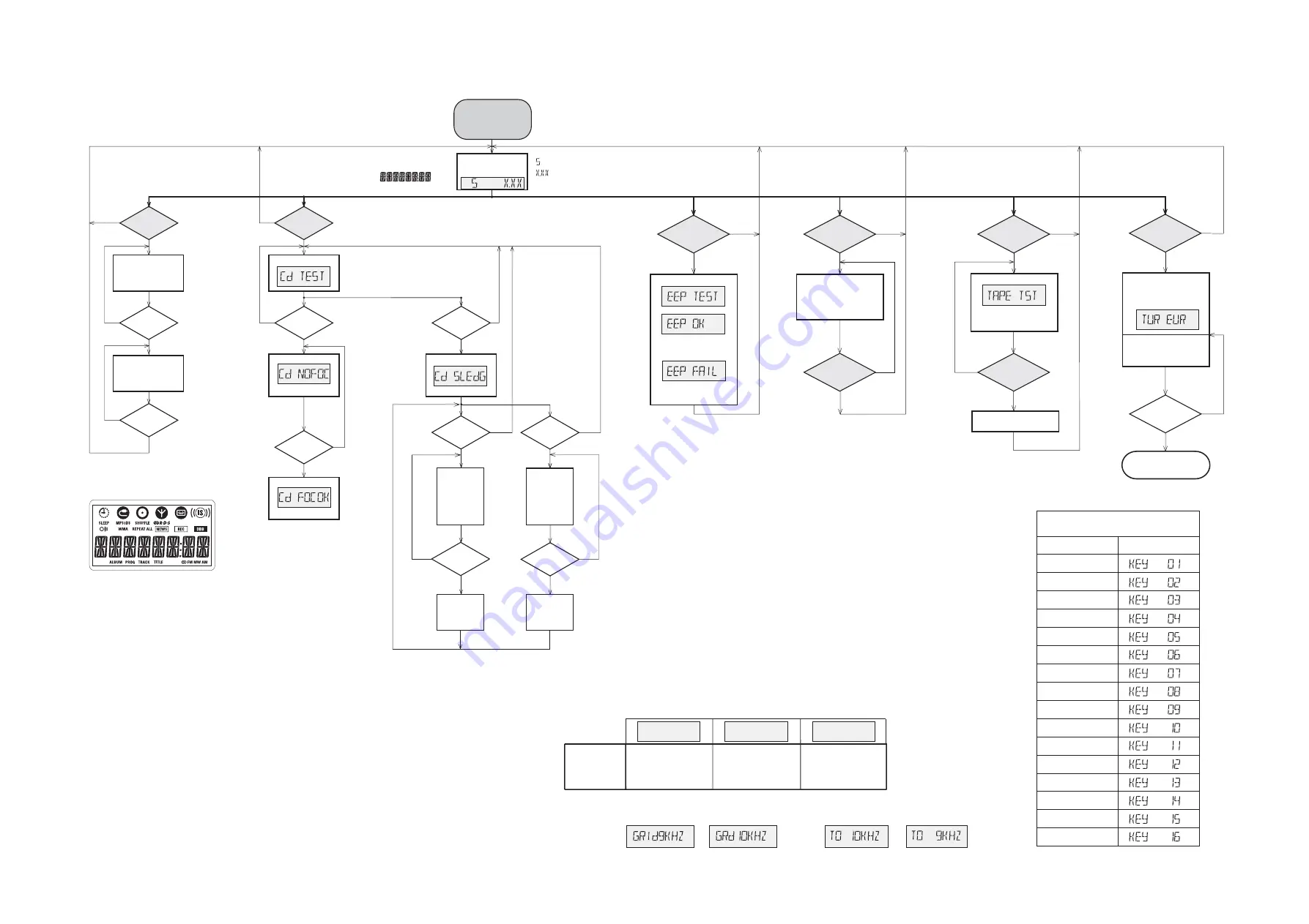
SERVICE TEST PROGRAM
STOP
button pressed in any step returns
to begin of Service Testprogram.
PLAY
button
pressed?
STOP
button
pressed?
N
N
Y
Y
Y
Y
N
BLANK
DISPLAY TEST
CD SERVO TEST
Display shows
version number
of the µP - software.
NEXT
button
pressed?
Display shows
ALBUM DN
pressed?
Slide moves
outwards as
long as button
is held
depressed.
PLAY
button
pressed?
ALBUM UP
pressed?
Y
Y
N
N
FOCUS found?
Y
N
Display shows
FOCUS search
SLIDE MOTOR test
To enter Service
Testprogram hold
PLAY & DISPLAY
buttons
depressed while
plugging mainscord in.
*
Door switch is ignored
m
CD door can be opened.
is software version, eg. S 4.15
N
*
Tuner test the sound settings
Volume up/down
,
DSC
,
IS and DBB
function as in normal mode,
but flags will not be indicated on the display in all steps.
stands for Service mode,
N
Y
FORMAT EEPROM
Display shows
if it is fail,
skip to
EEPROM is cleared and
default values are stored.
DISPLAY
button
pressed?
This test should be done at the
end of the production process
so that every set is customised
before leaving factory.
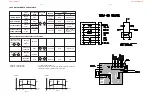
table 2
EUROPE
FM/MW
USA
FM/MW
OVERSEAS
FM/MW
REGION
&
SET VERSIONS
1)Grid switchable
100/10kHz - 50/9kHz
/22/25
/37
/21/21M/30
TUNER VERSIONS
1)
To toggle frequency grid press
BAND
button for more than 5s in normal tuner mode (
not
in service testmode)
.
Display will show either or , and show or
when button released.
N
Y
TAPE TEST
Display shows
Solenoids of the deck
are activated for 2s and
deactivated for 3s.
Switch all actions off
REC
button
pressed?
PLAY/DISPLAY
button
pressed?
PLAY/DISPLAY
button
pressed?
N
Y
TUN OSE
TUN USA
TUN EUR
Display shows
Enter sledge test
NEXT button
pressed?
Y
PREV button
pressed?
Y
N
N
Enter focus test
Display shows
disc motor turns
PLAY button
pressed?
Y
Slide stops
moving
N
Slide moves
inwards as
long as button
is held
depressed.
PLAY button
pressed?
Y
Slide stops
moving
N
skip to
N
SOURCE TEST
N
Display shows version
of tuner board as long as
PROGRAM
key will be
pressed.
Tuner is normal working
except for the
PROGRAM
button.
POWER
switched off?
KEY TEST
Button
Display
Power
Clock set
Program
Band
Play
.
-
RECORD
SOURCE
IS
DSS
VOL DOWN
VOL DOWN
Table1
N
Y
Exit Service Testprogram
e.g.
N
Y
Y
KEY TEST
SOURCE
button
pressed?
This test should be done at the
end of the production process
so that every set is customised
before leaving factory.
Press every buttons,
Display shows
(See table 1)
PRESET UP
pressed?
Display shows all
segments and flags
for checking open circuits.
see figure 1
IS
- LED is switched on.
www.nostatech.nl
www.nostatech.com
Summary of Contents for MCM390
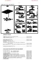
Page 2: ...1 1 HANDLING CHIP COMPONENTS www nostatech nl www nostatech com ...
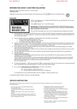
Page 3: ...1 2 www nostatech nl www nostatech com ...
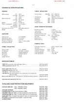
Page 4: ...2 1 www nostatech nl www nostatech com ...
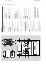
Page 6: ...3 1 CONNECTION AND CONTROLS www nostatech nl www nostatech com ...
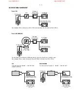
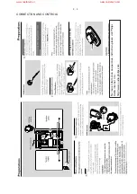
Page 12: ...5 2 5 2 www nostatech nl www nostatech com ...
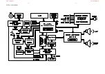
Page 14: ...6 1 6 1 SET BLOCK DIAGRAM www nostatech nl www nostatech com ...
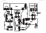
Page 15: ...6 2 6 2 SET WIRING DIAGRAM www nostatech nl www nostatech com ...
Page 16: ...7 1 7 1 CIRCUIT DIAGRAM DISPLAY AND MCU BOARD www nostatech nl www nostatech com ...
Page 22: ...9 1 9 1 CIRCUIT DIAGRAM CASSETTE BOARD www nostatech nl www nostatech com ...
Page 25: ...10 1 10 1 CIRCUIT DIAGRAM CD BOARD PART 1 www nostatech nl www nostatech com ...
Page 26: ...10 2 10 2 CIRCUIT DIAGRAM CD BOARD PART 2 www nostatech nl www nostatech com ...
Page 30: ...11 1 11 1 CIRCUIT DIAGRAM MAIN and POWER BOARD www nostatech nl www nostatech com ...
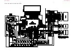
Page 31: ...11 2 11 2 LAYOUT DIAGRAM MAIN BOARD COMPONENT SIDE www nostatech nl www nostatech com ...
Page 32: ...11 3 11 3 LAYOUT DIAGRAM MAIN BOARD COPPER SIDE www nostatech nl www nostatech com ...
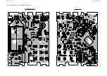
Page 33: ...11 4 11 4 LAYOUT DIAGRAM POWER BOARD www nostatech nl www nostatech com ...
Page 34: ...12 1 12 1 EXPLODED VIEW DIAGRAM 66 65 67 70 71 72 www nostatech nl www nostatech com ...


