xx
4 - 2
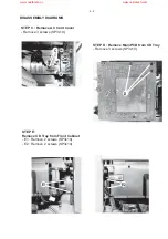
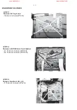
DISASSEMBLY DIADRAMS
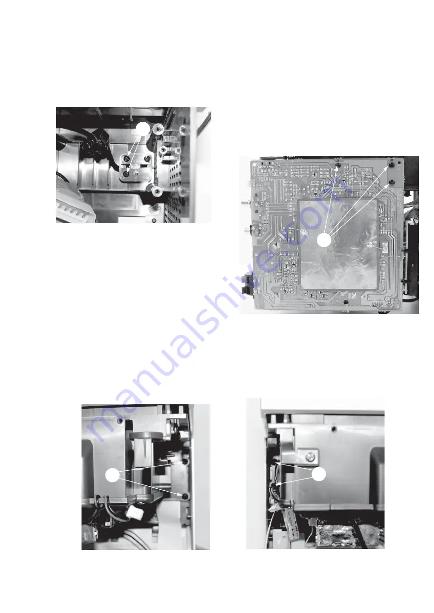
C
STEP C : Remove AC Cord Cover
- Remove 3 screws (SP3x10)
D
STEP D : Remove Main PCB from CD Tray
- Remove 3 screws (SP3x10)
E1
E2
STEP E :
Remove CD Tray from Front Cabinet
- E1 : Remove 2 screws (SP3x10)
- E2 : Remove 2 screws (SP3x10)
www.nostatech.nl
www.nostatech.com
Summary of Contents for MCM390
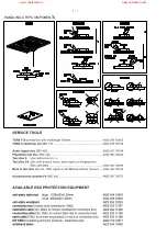
Page 2: ...1 1 HANDLING CHIP COMPONENTS www nostatech nl www nostatech com ...
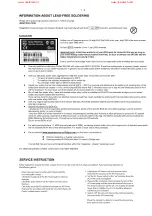
Page 3: ...1 2 www nostatech nl www nostatech com ...
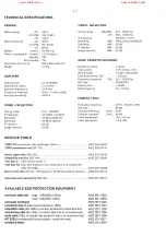
Page 4: ...2 1 www nostatech nl www nostatech com ...
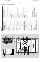
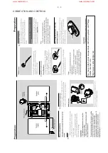
Page 6: ...3 1 CONNECTION AND CONTROLS www nostatech nl www nostatech com ...
Page 12: ...5 2 5 2 www nostatech nl www nostatech com ...
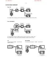
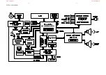
Page 14: ...6 1 6 1 SET BLOCK DIAGRAM www nostatech nl www nostatech com ...
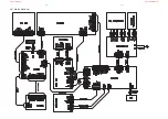
Page 15: ...6 2 6 2 SET WIRING DIAGRAM www nostatech nl www nostatech com ...
Page 16: ...7 1 7 1 CIRCUIT DIAGRAM DISPLAY AND MCU BOARD www nostatech nl www nostatech com ...
Page 22: ...9 1 9 1 CIRCUIT DIAGRAM CASSETTE BOARD www nostatech nl www nostatech com ...
Page 25: ...10 1 10 1 CIRCUIT DIAGRAM CD BOARD PART 1 www nostatech nl www nostatech com ...
Page 26: ...10 2 10 2 CIRCUIT DIAGRAM CD BOARD PART 2 www nostatech nl www nostatech com ...
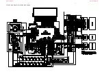
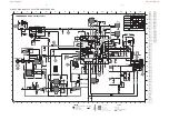
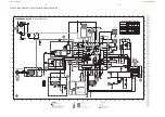
Page 30: ...11 1 11 1 CIRCUIT DIAGRAM MAIN and POWER BOARD www nostatech nl www nostatech com ...
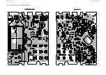
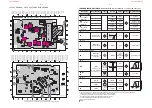
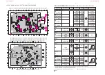
Page 31: ...11 2 11 2 LAYOUT DIAGRAM MAIN BOARD COMPONENT SIDE www nostatech nl www nostatech com ...
Page 32: ...11 3 11 3 LAYOUT DIAGRAM MAIN BOARD COPPER SIDE www nostatech nl www nostatech com ...
Page 33: ...11 4 11 4 LAYOUT DIAGRAM POWER BOARD www nostatech nl www nostatech com ...
Page 34: ...12 1 12 1 EXPLODED VIEW DIAGRAM 66 65 67 70 71 72 www nostatech nl www nostatech com ...


