MCM395
/12
©
Copyright 2008 Philips Consumer Electronics B.V. Eindhoven, The Netherlands
All rights reserved. No part of this publication may be reproduced, stored in a retrieval system or
transmitted, in any form or by any means, electronic, mechanical, photocopying, or otherwise without
the prior permission of Philips.
Published by SL 0822 Service Audio
Printed in The Netherlands
Subject to modification
Micro System
Version 1.1
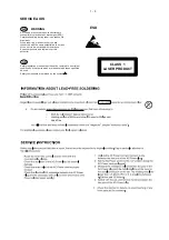
CLASS 1
LASER PRODUCT
©
3141 785 32501
TABLE OF CONTENTS
Page
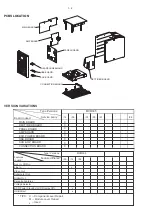
PCBs Location ...................................................................... 1-2
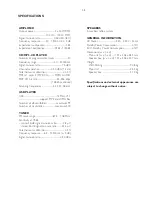
Specifi cations ....................................................................... 1-3
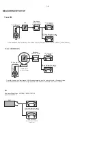
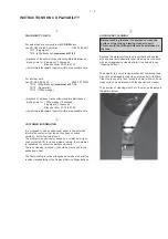
Measurement Setup ............................................................. 1-4
Service Aids, Safety Instruction, etc ...........................1-5 to 1-7
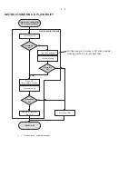
Software Version Checking ..................................................... 2
Set Block Diagram ................................................................... 3
Set Wiring Diagram ................................................................. 4
Main & Headphone & AUX Board............................................ 5
Panel Board ............................................................................. 6
AMP Board .............................................................................. 7
Rectifi er & USB Board ............................................................. 8
Set Mechanical Exploded View & Parts List ............................ 9
Revision List ........................................................................... 10
Summary of Contents for MCM395/12
Page 9: ...SET BLOCK WIRING DIAGRAM 3 1 4 1 ...
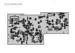
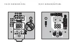
Page 10: ...5 1 5 1 PCB LAYOUT MAIN BOARD TOP VIEW ...
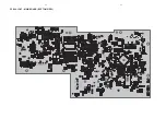
Page 11: ...PCB LAYOUT MAIN BOARD BOTTOM VIEW 5 2 5 2 ...
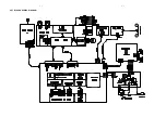
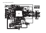
Page 12: ...5 3 5 3 CIRCUIT DIAGRAM MAIN BOARD PART1 ...
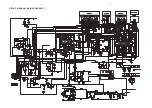
Page 13: ...5 4 5 4 CIRCUIT DIAGRAM MAIN BOARD PART2 ...
Page 14: ...5 5 5 5 PCB LAYOUT HEADPHONE BOARD TOP VIEW PCB LAYOUT HEADPHONE BOARD BOTTOM VIEW ...
Page 15: ...5 6 5 6 PCB LAYOUT AUX BOARD TOP VIEW PCB LAYOUT AUX BOARD BOTTOM VIEW ...
Page 16: ...5 7 5 7 CIRCUIT DIAGRAM HEADPHONE AUX BOARD ...
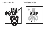
Page 17: ...6 1 6 1 PCB LAYOUT PANEL BOARD TOP VIEW ...
Page 18: ...PCB LAYOUT DISPLAY BOARD BOTTOM VIEW 6 2 6 2 ...
Page 19: ...6 3 6 3 CIRCUIT DIAGRAM PANEL BOARD ...
Page 20: ...7 1 PCB LAYOUT AMP BOARD TOP VIEW 7 1 ...
Page 21: ...7 2 PCB LAYOUT AMP BOARD BOTTOM VIEW 7 2 ...
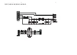
Page 22: ...7 3 CIRCUIT DIAGRAM AMP BOARD 7 3 ...
Page 23: ...8 1 PCB LAYOUT RECTIFIER BOARD TOP VIEW 8 1 ...
Page 24: ...8 2 PCB LAYOUT RECTIFIER BOARD BOTTOM VIEW 8 2 ...
Page 25: ...8 3 CIRCUIT DIAGRAM RECTIFIER BOARD 8 3 ...
Page 26: ...8 4 PCB LAYOUT USB BOARD TOP VIEW 8 4 PCB LAYOUT USB BOARD BOTTOM VIEW ...


