background image

5

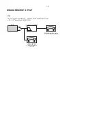
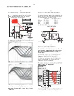
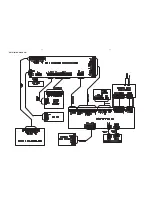
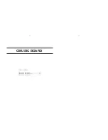
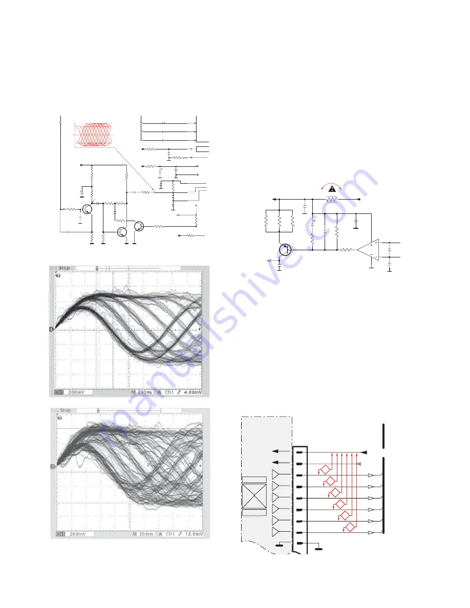
EYE-PATTERN SIGNAL – JITTER MEASUREMENT

Measure the signal on the input of the Signal processor
using an 

analog

oscilloscope. Please find the exact

measuring point in your Service Manual.

See below examples of the signal. Amplitude should read at
least 700mVpp using SBC444A.

good

bad

If the oscilloscope shows a signal like the ‘bad’ one, and/or
the amplitude decreases within 1 minute - the CD drive has
to be replaced.

6

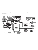
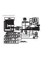
CD DRIVE – LASER CURRENT MEASUREMENT

The laser current can be measured as a voltage drop on a
resistor. The resistor is marked in every Service Manual.
The value depends on the type of CD drive.

typical value

most probably defect

VAMxxxx

: 150-230mV

350mV

MCDxx

: 170-230mV

300mV

DA1x

: 210-250mV

350mV

DA2x

: 175-200mV

250mV

Use SBC444A (CD-DA) for measurement.

7

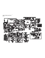
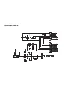
CD DRIVE – OFFSET MEASUREMENT

The photodiodes of the CD-drive may have an offset. These
offsets have to be compensated by the signal processor.
High offsets can lead to poor playability of some CDs
(skipping tracks).

To measure the offset values, start the 

Service Test

Program

- section “Focus Test” without a CD.

The offsets can be measured with a DC Millivoltmeter
directly on the connector (see drawing below). Pin
numbering varies from drive to drive.

The values from diode A-D should read 0±10mV.
Diodes E and F are less critical.

If one of the offsets is higher than ±10mV the CD drive has
to be replaced. Otherwise replace the Signal Processor.

Sanyo DA12T3

CD Drive

A

A

F

C

B

E

C

D

E

VCC

B

VREF

F

D

9

10

11

12

13

14

15

16

1800

+5V_HF

VrefCD10

A

D

E

B

C

F

GND

8

E

D

A

B

C

F

Laser power control

100n

2878

470n

2876

3821

1R

1K

3823

2880

33p

+5V

BC807-40

7879

3817

47R

3820

4R7

47R

3819

1n

2879

2877

47u

1

8

4

7811-A

LM358D

3

2

10K

3822

47R

3818

2841

100n

47n

2869

+5V_HF

LASER DIODE

U >250mV

->Laser damaged !

4,6V

3V

3,3V

3,9V

2V

0,17V

0,17V

Sanyo

DA12T3

HF-Amplifier

D3

D2

D1

Drive detection

680R

3905

3903

3K3

BC847B

7877

47n

2818

1K5

3902

5

7

4

2

1

6

3

64

8

9

10

11

470R

3893

+3.3V

2K2

3908

10K

3923

BC847B

7878

BC847B

7876

4n7

2813

3896

100R

220u

2885

2881

560p

47n

2887

560R

3901

2883

470n

2817

4u7

3n3

2814

3898

220R

3895

27K

470n

2884

+3.3V

3909

820R

3907

100R

3920

33K

3897

2882

82p

3K3

3904

2K7

3899

3906

470R

+5V_HF

HFIN

VrefCD10

100p

2815

2816

22n

LD

ON

to 3826,3827

VREF GE

VDDA1

VRIN

VSSA1

ISLICE

LD

ON

D1

D2

D3

D4

HFIN

HFREF

IREF

CD_DA: 0V / CD_RW: 3V

Σ

 (A-D)

800mVpp

TB = 0.5

µ

s/div

EYE-PATTERN

1,8V

1,2V

2,4V

2,6V

0,65V

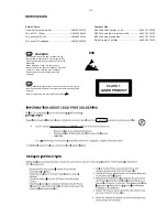
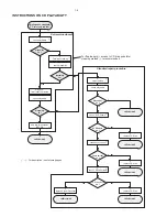
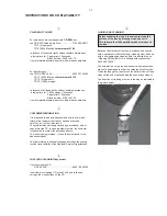
INSTRUCTIONS ON CD PLAYABILITY

1-8

Summary of Contents for MCM398D Series

Page 1: ...ed by SL 0724 Service Audio Printed in The Netherlands Subject to modification Micro System Version 1 1 CLASS 1 LASER PRODUCT 3141 785 31831 TABLE OF CONTENTS Page PCBs Location 1 2 Specifications 1 3 Measurement Setup 1 4 Service Aids Safety Instruction etc 1 5 CD Playability Test 1 6 to 1 8 Software Version Checking 2 Set Block Diagram 3 Set Wiring Diagram 4 Main HP AUX Board 5 Front Display USB...

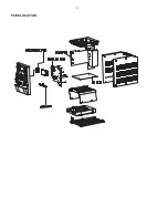
Page 2: ...1 2 PCBS LOCATION ...

Page 3: ... 44 1 48 kHz USB PLAYER USB 12 Mb s V1 1 support MP3 and WMA files Number of albums folders maximum 99 Number of tracks titles maximum 500 FM FM wave range 87 5 108 MHz Sensitivity at 75 mono 26 dB signal to noise ratio 2 8 µV stereo 46 dB signal to noise ratio 61 4 µV Selectivity t 28 dB Total harmonic distortion d 5 Frequency response 63 12500 Hz 3 dB Signal to noise ratio t 50 dBA SPEAKERS 2 wa...

Page 4: ...LEVEL METER e g Sennheiser UPM550 with FF filter S N and distortion meter e g Sound Technology ST1700B DUT CD Use Audio Signal Disc SBC429 4822 397 30184 replaces test disc 3 L P F 13 th order filter 4822 395 30204 MEASUREMENT SETUP ...

Page 5: ...ICE AIDS GB WARNING All ICs and many other semi conductors are susceptible to electrostatic discharges ESD Careless handling during repair can reduce life drastically When repairing make sure that you are connected with the same potential as the mass of the set via a wrist wrap with resistance Keep components and tools also at this potential ESD CLASS 1 LASER PRODUCT GB Safety regulations require ...

Page 6: ...ce CD Drive Laser current ok N Y check Laser current CD Drive offsets ok N Y check CD Drive offsets clean the lens check playability return set Customer complaint CD related problem return set return set replace CD Drive return set replace CD Drive return set replace Signal Processor return set fast lens cleaning 1 2 3 4 5 6 7 For flap loaders access to CD drive possible cleaning method 4 is recom...

Page 7: ...o contact the workshop directly The lens cleaning method 3 should be mentioned in the addendum sheet The final wording in national language as well as the printing is under responsibility of the Regional Service Organizations 3 FAST LENS CLEANING dry brush Use lens cleaning CD SBC AC300 9082 100 00043 Insert the lens cleaning CD press PLAY and follow the voice guide s instructions on the CD 4 LIQU...

Page 8: ... a DC Millivoltmeter directly on the connector see drawing below Pin numbering varies from drive to drive The values from diode A D should read 0 10mV Diodes E and F are less critical If one of the offsets is higher than 10mV the CD drive has to be replaced Otherwise replace the Signal Processor Sanyo DA12T3 CD Drive A A F C B E C D E VCC B VREF F D 9 10 11 12 13 14 15 16 1800 5V_HF VrefCD10 A D E...

Page 9: ...rsion 1 Press and hold DISPLAY and SOURCE buttons then plug A C to power on LCD Display shows existing software version S 0 12 2 During shows S 0 12 press STOP button to show firmware version SOFTWARE VERSION CHECKING 2 1 2 1 ...

Page 10: ...3 1 3 1 SET BLOCK DIAGRAM ...

Page 11: ...SET WIRING DIAGRAM 4 1 4 1 ...

Page 12: ...IN BOARD TABLE OF CONTENTS Main PCB Layout Top View 5 2 Main PCB Layout Bottom View 5 3 Main PCB Circuit Diagram Part1 5 4 Main PCB Circuit Diagram Part2 5 5 Headphone AUX PCB Circuit Diagram 5 6 5 1 5 1 ...

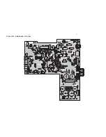
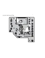
Page 13: ...5 2 5 2 PCB LAYOUT MAIN BOARD TOP VIEW ...

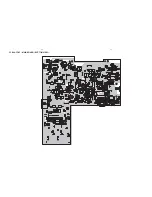
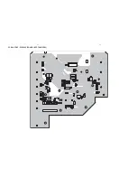
Page 14: ...PCB LAYOUT MAIN BOARD BOTTOM VIEW 5 3 5 3 ...

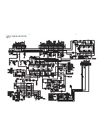
Page 15: ...5 4 5 4 CIRCUIT DIAGRAM MAIN BOARD PART1 ...

Page 16: ...5 5 5 5 CIRCUIT DIAGRAM MAIN BOARD PART2 ...

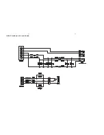
Page 17: ...5 6 5 6 CIRCUIT DIAGRAM HP AUX BOARD ...

Page 18: ...FRONT DISPLAY USB JACK BOARD TABLE OF CONTENTS Display PCB Layout Top View 6 2 Display PCB Layout Bottom View 6 3 Display PCB Circuit Diagram 6 4 USB PCB Circuit Diagram 6 5 6 1 6 1 ...

Page 19: ...6 2 6 2 PCB LAYOUT DISPLAY BOARD TOP VIEW ...

Page 20: ...PCB LAYOUT DISPLAY BOARD BOTTOM VIEW 6 3 6 3 ...

Page 21: ...6 4 6 4 CIRCUIT DIAGRAM FRONT DISPLAY BOARD ...

Page 22: ...6 5 6 5 CIRCUIT DIAGRAM USB BOARD ...

Page 23: ...CMUSIC BOARD TABLE OF CONTENTS CMUSIC PCB Layout Top View 7 2 CMUSIC PCB Layout Bottom View 7 3 CMUSIC PCB Circuit Diagram 7 4 7 1 7 1 ...

Page 24: ...7 2 PCB LAYOUT CMUSIC BOARD TOP VIEW 7 2 ...

Page 25: ...7 3 PCB LAYOUT CMUSIC BOARD BOTTOM VIEW 7 3 ...

Page 26: ...7 4 CIRCUIT DIAGRAM CMUSIC BOARD CD TUNER PART 7 4 ...

Page 27: ...7 5 CIRCUIT DIAGRAM CMUSIC BOARD USB PART 7 5 ...

Page 28: ...8 1 8 1 SET MECHANICAL EXPLODED VIEW ...

Page 29: ...ER NANO INJ 7 996510001448 STANDBY BOTTON LIGHT GUIDE L 996510001916 IPOD HOLDER 20GB INJ 8 996510004571 CONTROL KEY DOCKING M 996510001917 IPOD HOLDER 30GB PHOTO INJ 22 996510004566 TOP CABINET N 996510001918 IPOD HOLDER 30GB VIDEO INJ O R E V O C P O T 5 7 5 4 0 0 0 1 5 6 9 9 3 2 994000005786 CD MECHANISM DA11VF SANYO 24 996510004581 25 996510004569 30 996510000868 CD DAMPER PINK 658F 31 9965100...

Page 30: ...CRYSTAL 14 318 MHZ 20PF ZD2001 994000005744 ZENER DIODE 5V1 1 2W D201 996510001053 RECTIFIER DIODE RL201 IC201 996510001057 IC S1117 33PIC TO 220F 3SL IC202 996510001058 IC S7806PI TO 220F FRONT USB BOARD IC301 996510004564 POWER AMPLIFIER IC TDA8922BJ CON102 996510001071 USB JACK 4P ANGLE TYPE IC401 996510004563 I C LM324DG SOIC 14 D101 996510001072 LED INDICATOR D3 CLEAR BLUE D102 996510001072 L...

Page 31: ... 996510004565 CHIP VARISTOR 14V 270PF ZD406 996510004565 CHIP VARISTOR 14V 270PF ZD407 996510004565 CHIP VARISTOR 14V 270PF ZD408 996510004565 CHIP VARISTOR 14V 270PF ZD501 996510004559 DIODE 8V2 1 2W TCLLZ8V2 LL34 Note Only these parts mentioned in the list are normal service parts 8 4 ...

Page 32: ...9 1 REVISION LIST 1 0 Manual 3141 785 31830 Initial Service Manual released 1 1 Manual 3141 785 31831 In this version version 05 added 1 P8 2 Mechanical and Accessories Partslist updated ...

Reviews: