Version 1.5
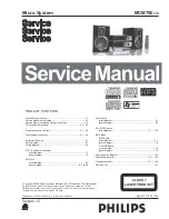
MCM700
/12
©
3141 785 31755
Micro System
Published by SL 0839 Service Audio Subject to modification
©
Copyright 2008 Philips Consumer Electronics B.V. Eindhoven, The Netherlands
All rights reserved. No part of this publication may be reproduced, stored in a retrieval
system or transmitted, in any form or by any means, electronic, mechanical, photocopying,
or otherwise without the prior permission of Philips.
Technical specification .................................................................. 1-1
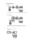
Service measurement setup ......................................................... 2-1
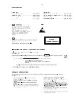
Service aids & Leadfree & safety information .............................. 2-2
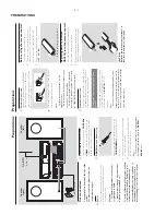
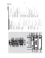
Preparations and Controls .................................................... 3-1...3-3
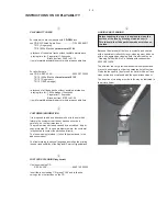
Disassembly Instruction ....................................................... 4-1...4-2
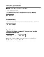
Software Checking ........................................................................ 5-1
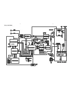
Block diagram................................................................................ 6-1
Wiring diagram ............................................................................. 6-2
VFD / Key Board Assembly
circuit
diagram
.......................................................................... 7-1
layout
diagram
.......................................................................... 7-2
CD Block
circuit
diagram
.......................................................................... 8-1
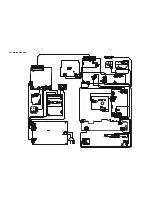
layout diagram ................................................................ 8-2 to 8-3
Tuner board
circuit
diagram.
......................................................................... 9-1
layout
diagram
.......................................................................... 9-2
CD / MPEG board
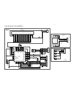
circuit diagram .............................................................. 10-1...10-4
AMP Block
circuit
diagram.........................................................................11-1
layout
diagram
.........................................................................11-2
Exploded view diagram ............................................................... 12-1
Mechanical partslist ........................................................... 12-2...12-3
Electrical partslist .............................................................. 13-1...13-2
TABLE OF CONTENTS
CLASS 1
LASER PRODUCT
AMP Board
circuit diagram........................................................................ 11-3
layout
diagram
.........................................................................11-4
Pre-AMP Board
Revision List ................................................................................ 14-1
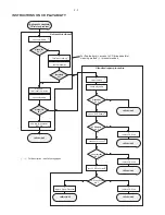
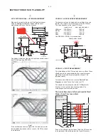
CD Playability Checking ....................................................... 2-3...2-5
Summary of Contents for MCM700/12
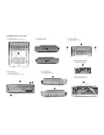
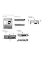
Page 11: ...4 1 4 1 DISASSEMBLY INSTRUCTION CD PART ...
Page 12: ...4 2 4 2 DISASSEMBLY INSTRUCTION TUNER AMP PART ...
Page 14: ...6 1 6 1 SET BLOCK DIAGRAM ...
Page 15: ...6 2 6 2 SET WIRING DIAGRAM ...
Page 17: ...7 2 7 2 LAYOUT DIAGRAM VFD KEY BOARD ASSEMBLY COMPONENT SIDE ...
Page 18: ......
Page 19: ...8 2 8 2 LAYOUT DIAGRAM CD BLOCK COMPONENT SIDE ...
Page 21: ...9 2 9 2 LAYOUT DIAGRAM TUNER BOARD ...