
1 - 1
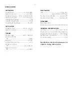
AMPLIFIER
Output power ....................................... 2 x 50 W RMS
Signal-to-noise ratio .......................................
t
70 dBA
Frequency response ...... 20 Hz – 20 KHz, ± 3 dB
Input sensitivity AUX ....................... 0.5 V (max. 2 V)
Impedance loudspeakers ......................................... 4
:
Impedance headphones ........................................ 32
:
Output power headphones ....................... <50 mW
CD PLAYER
Frequency range ................................ 20 Hz – 20 kHz
Signal-to-noise ratio ............................................ 70 dBA
TUNER
FM wave range ................................... 87.5 – 108 MHz
Sensitivity at 75
:
– FM ................................................................................ 20dBf
Selectivity .................................................................
t
25 dB
Total harmonic distortion .....................................
d
1%
Frequency response
– FM .............................................................. 63 – 6000 Hz
Signal-to-noise-ratio
– FM .......................................................................
t
50 dBA
USB PLAYER
USB ................................................................... 12Mb/s, V1.1
......................................... support MP3 and WMA files
Number of albums/folders ................. maximum 99
Number of tracks/titles ...................... maximum 400
SPEAKERS
Bass reflex system
Dimensions (w x h x d) . 145 x 230 x 215 (mm)
GENERAL INFORMATION
AC Power ..................................... 230 – 240 V / 50 Hz
Dimensions (w x h x d) . 208 x 156 x 268 (mm)
Weight(with/without speakers) ...... 4.30 / 2.31 kg
Standby power consumption ............................ <7 W
Eco power standby ................................................. <1 W
Specifications and external appearance are
subject to change without notice.
SPECIFICATION
Summary of Contents for MCM700/12
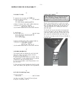
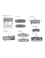
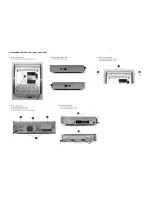
Page 11: ...4 1 4 1 DISASSEMBLY INSTRUCTION CD PART ...
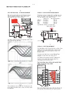
Page 12: ...4 2 4 2 DISASSEMBLY INSTRUCTION TUNER AMP PART ...
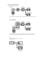
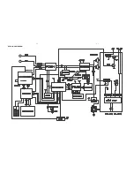
Page 14: ...6 1 6 1 SET BLOCK DIAGRAM ...
Page 15: ...6 2 6 2 SET WIRING DIAGRAM ...
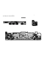
Page 17: ...7 2 7 2 LAYOUT DIAGRAM VFD KEY BOARD ASSEMBLY COMPONENT SIDE ...
Page 18: ......
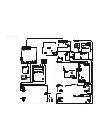
Page 19: ...8 2 8 2 LAYOUT DIAGRAM CD BLOCK COMPONENT SIDE ...
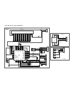
Page 21: ...9 2 9 2 LAYOUT DIAGRAM TUNER BOARD ...