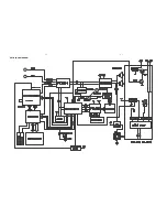
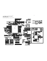
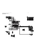
FL IN
FR IN
MUTE
+12V
R313
560
Q300
BC817B
R303
2.2K
R300
4.7K
L303
JRH0349
L304
JRH0349
VSSA2
1
VDDA2
3
VSSD
24
STABL
18
PROT
13
SUB/VSSD
19
VDDP2
23
VSSP2
20
BOOT2
22
OUT2
21
OUT1
16
BOOT1
15
VSSP1
17
VDDP1
14
MODE
6
OSC
7
VSSA1
12
VDDA1
10
IN1+
8
IN1-
9
SGND1
11
SGND2
2
1N2+
5
IN2-
4
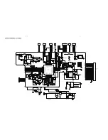
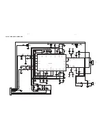
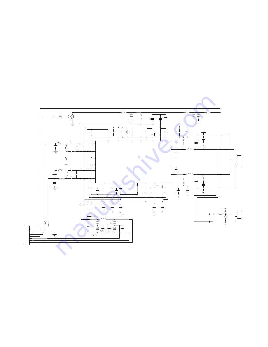
IC300
TDA8920BTH
C355
104
C356
104
C360
104
C374
104/100V
C361
104
C363
104
C364
104
VssA2
VddA2
Vddp2
C379
153
C383
684(M)
C373
104
R312
22
C377
153
C382
684(M)
C362
104
R311
22
SL-OUT
SR-OUT
C347
220P
C341
474
C339
474
R305
5.6K
R309
5.6K
L300
47uH
L301
47uH
C371
104
C370
104
C381
153
C392
224
C376
104/100V
C345
220P
R308
5.6K
R306
5.6K
C344
474
C342
474
1
2
3
4
CN300
4p/2.5
C331
102
C332
102
C333
102
C335
102
C336
102
C330
102
C324
102
C326
102
C327
102
C329
102
R318
10
R317
10
C348
220P
C350
220P
C353
220P
C354
220P
Vddp2
Vssp2
Vssp2
Vddp2
C388
470uf/35v
C387
470uf/35v
C384
22uf/100V
C367
104
C368
104
R319
10
R320
10
+28V
-28V
C390
1000uf/35v
C389
1000uf/35v
V
ssp2
R314
22K
R315
22K
R310
22
C359
104
R316
30k
R304
5.6K
DZ300
5.1V
C338
100UF/16V
-28V
+28V
+12V
GND
GND
1
2
3
4
5
6
7
8
CN301
8P/2.0
GND
GND
C300
10uF
D300
4001
D301
4001
R321
100
C393
220uF
1
2
CN303
2.5/2P
SL-OUT
SR-OUT
R322
120
+12V
spart
FAN
R338
X R339
X
L-O
R-
O
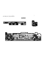
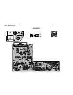
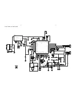
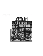
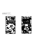
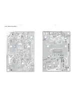
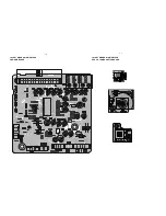
LAYOUT DIAGRAM - AMP BOARD
11 - 1
11 - 1
Summary of Contents for MCM700/12
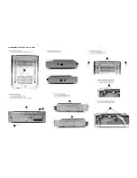
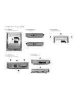
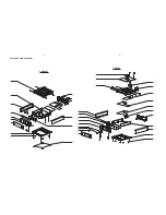
Page 11: ...4 1 4 1 DISASSEMBLY INSTRUCTION CD PART ...
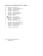
Page 12: ...4 2 4 2 DISASSEMBLY INSTRUCTION TUNER AMP PART ...
Page 14: ...6 1 6 1 SET BLOCK DIAGRAM ...
Page 15: ...6 2 6 2 SET WIRING DIAGRAM ...
Page 17: ...7 2 7 2 LAYOUT DIAGRAM VFD KEY BOARD ASSEMBLY COMPONENT SIDE ...
Page 18: ......
Page 19: ...8 2 8 2 LAYOUT DIAGRAM CD BLOCK COMPONENT SIDE ...
Page 21: ...9 2 9 2 LAYOUT DIAGRAM TUNER BOARD ...