2 - 1
SERVICE MEASUREMENT
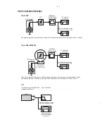
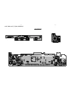
Bandpass
250Hz-15kHz
e.g. 7122 707 48001
LF Voltmeter
e.g. PM2534
DUT
RF Generator
e.g. PM5326
S/N and distortion meter
e.g. Sound Technology ST1700B
Tuner FW
Use a bandpass filter to eliminate hum (50Hz, 100Hz) and disturbance from the pilottone (19kHz, 38kHz).
Ri=50
?
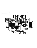
Bandpass
250Hz-15kHz
e.g. 7122 707 48001
LF Voltmeter
e.g. PM2534
DUT
S/N and distortion meter
e.g. Sound Technology ST1700B
Frame aerial
e.g. 7122 707 89001
Tuner AM (MW,LW)
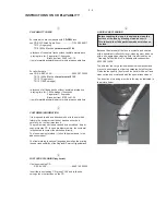
To avoid atmospheric interference all AM-measurements have to be carried out in a Faraday?s cage.
Use a bandpass filter (or at least a high pass filter with 250kHz) to eliminate hum (50Hz, 100Hz).
RF Generator
e.g. PM5326
Ri=50
?
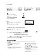
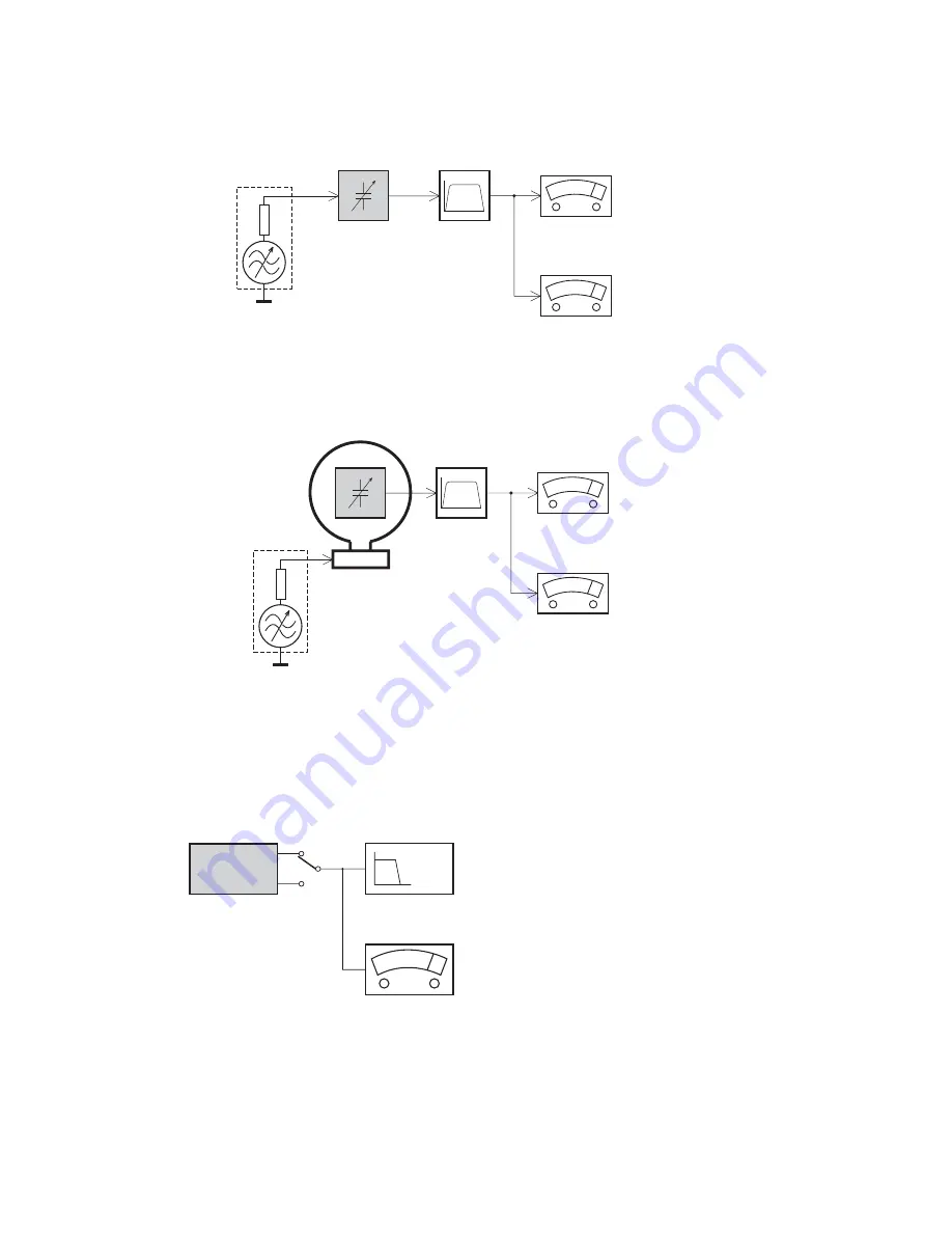
L
R
LEVEL METER
e.g. Sennheiser UPM550
with FF-filter
S/N and distortion meter
e.g. Sound Technology ST1700B
DUT
CD
RECORDER
Use Audio Signal Disc SBC429 4822 397 30184
(replaces test disc 3)
Use Universal Test Cassette
Fe
SBC420 4822 397 30071
L
R
LEVEL METER
e.g. Sennheiser UPM550
with FF-filter
S/N and distortion meter
e.g. Sound Technology ST1700B
DUT
LF Generator
e.g. PM5110
Ri=50
?
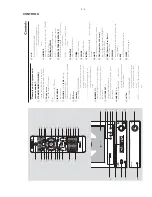
Summary of Contents for MCM700/12
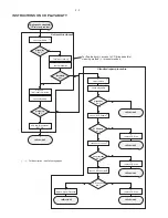
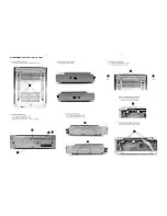
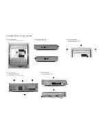
Page 11: ...4 1 4 1 DISASSEMBLY INSTRUCTION CD PART ...
Page 12: ...4 2 4 2 DISASSEMBLY INSTRUCTION TUNER AMP PART ...
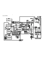
Page 14: ...6 1 6 1 SET BLOCK DIAGRAM ...
Page 15: ...6 2 6 2 SET WIRING DIAGRAM ...
Page 17: ...7 2 7 2 LAYOUT DIAGRAM VFD KEY BOARD ASSEMBLY COMPONENT SIDE ...
Page 18: ......
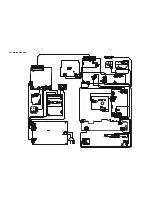
Page 19: ...8 2 8 2 LAYOUT DIAGRAM CD BLOCK COMPONENT SIDE ...
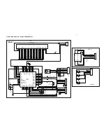
Page 21: ...9 2 9 2 LAYOUT DIAGRAM TUNER BOARD ...


