
14 -1
REVISION LIST
1.0 Manual 3141 785 31750
Initial Service Manual released.
1.1 Manual 3141 785 31751
In this version,
1) the instruction of CD playability check is added.
2) Chapter11 has been revised according to latest diagrams.
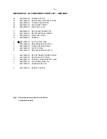
4) P12-2 & P12-3 Mechanical and Accessories Partslist updated.
5) P13-1 & P13-2 Electrical Partslist updated.
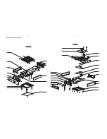
3) P12-1 Set Mechanical Exploded View has been revised according to latest information.
1.2 Manual 3141 785 31752
In this version,
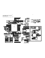
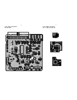
1) Chapter11 AMP Board diagrams has been revised according to latest information.
1.3 Manual 3141 785 31753
In this version,
1) P5-1 Software version checking updated.
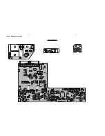
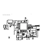
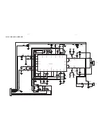
2) P8-1 CD BLOCK Circuit Diagram updated.
3) P11-3 AMP Block Circuit Diagram revised.
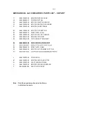
4) P12-3 CD Mechanical Partslist updated.
1.3 Manual 3141 785 31754
In this version,
1) P12-3 CD Mechanical Partslist updated.
33 996510003603 SERVO PCB ASS’Y M5671U-A1
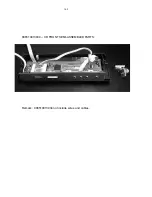
70 996510013934 CD FRONT SEMI-ASSEMBLED PARTS (Refer to Page 14-2 picture)
Add:
A
SWITCH BOARD ASS'Y MCM700
B
DISPLAY BOARD ASS'Y MCM700
C
USB BOARD ASS'Y MCM700
D
FUNCTION KNOB COVER
E
FUNCTION KNOB COVER
F
SWITCH KNOB(4-DIRECTIONS)
G
MCM700 USB DOOR SPRING
H
DVD KEY-PRESS PLATE(ALUMINIUM)
I
FUNCTION KNOB RING
J
MCM700 DVD FRONT COVER
K
POWER BUTTON
L
MCM700 USB BRACKET
M
MCM700 USB COVER
N
PANEL PAD H=4.5
O
MCM700/12 DISPLAY LENS
P
BLACK SPONGE 35X6X1 40°
Q
METAL PLATE 11X7X1 D3
R
SCREW 2.6X8 FA (PLATING)
S
SCREW 2.6X6 PT (PLATING)
T
SCREW 2.6X8 PT (PLATING)
Remark: 996510013934 include the materials as below:
1.3 Manual 3141 785 31755
In this version,
1) P13-2 ELECTRICAL PARTS LIST - CD PART (CPU PCB ASS'Y MCM700) updated.
L1 996510019915 FIXED INDUCTOR 200UH 6X5
Add:
Summary of Contents for MCM700/12
Page 11: ...4 1 4 1 DISASSEMBLY INSTRUCTION CD PART ...
Page 12: ...4 2 4 2 DISASSEMBLY INSTRUCTION TUNER AMP PART ...
Page 14: ...6 1 6 1 SET BLOCK DIAGRAM ...
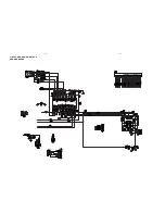
Page 15: ...6 2 6 2 SET WIRING DIAGRAM ...
Page 17: ...7 2 7 2 LAYOUT DIAGRAM VFD KEY BOARD ASSEMBLY COMPONENT SIDE ...
Page 18: ......
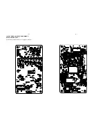
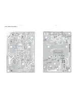
Page 19: ...8 2 8 2 LAYOUT DIAGRAM CD BLOCK COMPONENT SIDE ...
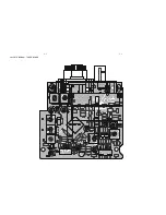
Page 21: ...9 2 9 2 LAYOUT DIAGRAM TUNER BOARD ...


