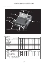
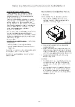
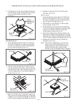
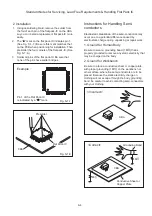
Technical Specification and Connection Facilities
1-9
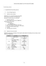
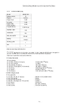
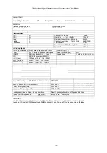
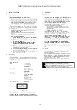
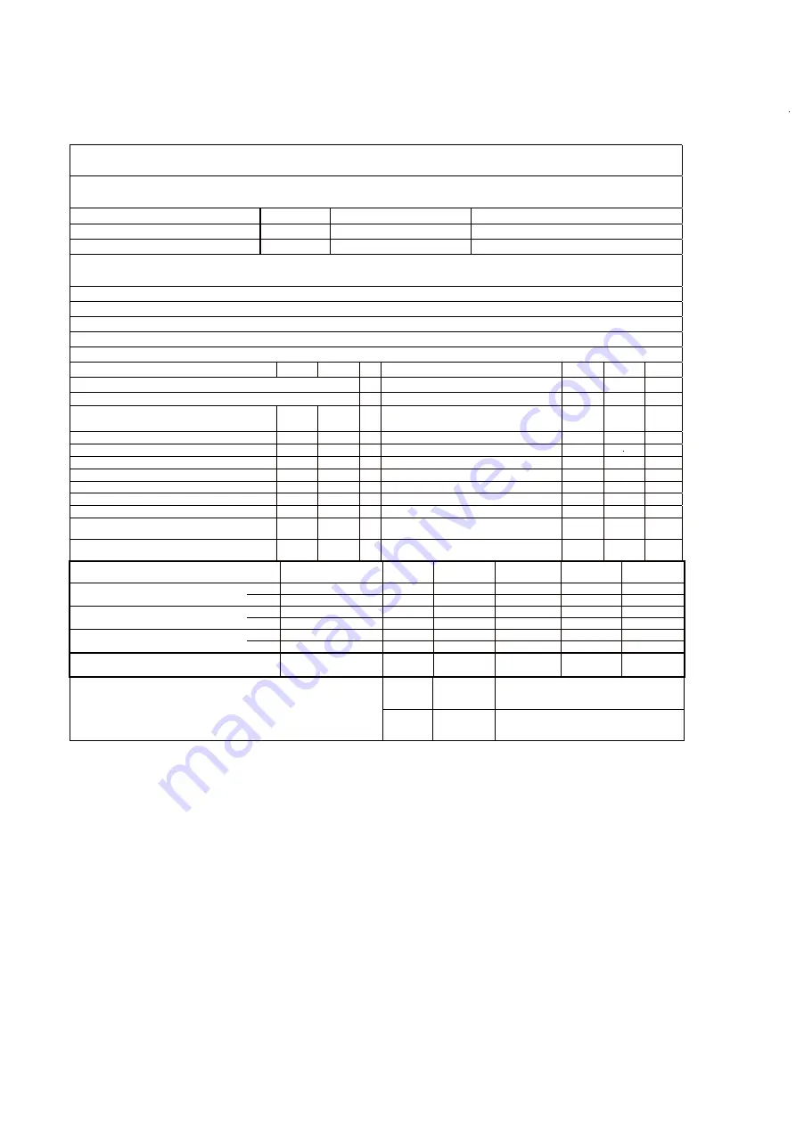
5.TUNER
FM use Silicon Lab Si4704/4705(w/RDS)
GENARAL PART
WAVE RANGE
VERSION
TOLERANCE
TUNING GRID
FM 87.5 – 108.00 MHz
/05/12
QUARTZ PRECISION
50kHz
AERIAL
FM
: PIG TAIL ANT WIR
(ȍ
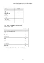
ELECTRICAL DATA
t
i
n
U
t
i
m
i
L
m
o
N
M
F
f
B
d
6
2
0
2
t
n
i
o
P
g
n
i
t
i
m
i
L
B
d
3
-
)
e
d
o
m
o
e
r
e
t
s
t
a
(
y
t
i
v
i
t
i
s
n
e
S
g
n
i
n
u
T
h
c
r
a
e
S
35
41
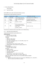
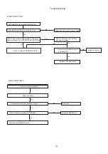
Search time digital tuning
system.
-
60
S
z
H
M
7
.
0
1
F
I
B
d
1
5
8
4
g
n
i
t
e
i
u
Q
B
d
6
4
-
o
e
r
e
t
S
5
4
0
5
m
u
H
n
o
i
t
a
l
u
d
o
M
5
4
0
5
o
i
t
a
R
N
/
S
B
d
4
-
0
e
s
r
e
v
e
R
n
o
i
t
a
c
i
f
il
p
m
A
%
3
2
)
z
H
k
5
7
.
v
e
D
q
r
F
,
V
m
1
F
R
(
n
o
i
t
r
o
t
s
i
D
Overall Frequency Response: 63Hz –
12.5KHz
-
±3
dB
Channel separation:400 / 1000 / 5000 Hz.
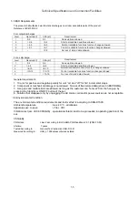
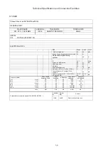
RF input: 68 dBf
26/30/
20
20/26/
18
dB
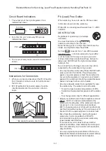
Frequency (MHz)
Noise Limited
Sensitivity 26 dB
Image
Rejection
IF Rejection
Large Signal
Handling
Selectivity
S9/300 kHz
FM
Nom.
18
30
64
1000
22
88.0
Lim.
22
25
45
500
18 (*1)
FM
Nom.
18
30
64
1000
22
98.0
Lim.
22
25
45
500
18 (*1)
FM
Nom.
18
30
60
116 dBf
45
107.0
Lim.
22
25
65
108 dBf
25
Units
dBf
DB
dB
mV/m
dB
Limited(d
B)
Normal
(dB)
Remark
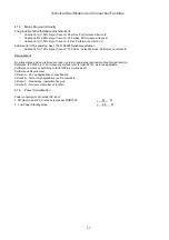
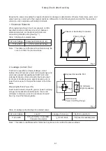
Susceptibility to unwanted signals(CPU,SMPS,AMP,DSP …):
-15dB
-20dB
Refer to selfpollution curve
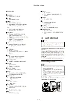
Summary of Contents for MCM7000/12
Page 30: ...AMP BOARD Layout Diagram 12 2 12 2 ...
Page 32: ...Display Board Layout Diagram 12 4 12 4 ...
Page 35: ...Key Board Layout Diagram 12 7 12 7 ...
Page 38: ...T5AH 250V Power Board Layout Diagram 12 10 12 10 ...
Page 42: ...Decoder Board Layout Diagram 12 14 12 14 ...
Page 44: ...Revision List Revision List Version 1 0 Initial Release 14 1 ...


