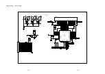
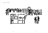
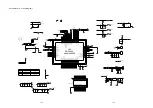
R33
R34
1K/0805
C16
471pF/50V
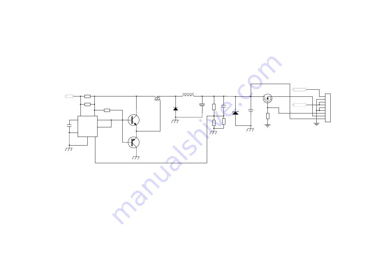
D12
SB560
L4
80uH/0.7mm
1000uF/10V
CE9
R37
9.1K/0805
R36
3K/0805
1
2
3
4
5
6
7
8
IC4
+9-16Vdc
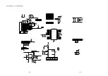
Q7
AF 9435P
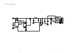
PIN1,2,3
PIN4
PIN5,6,7,8
Q6
C945 SOT-23
A733 SOT-23
Q5
R35
N/C
C15
N/O
C24
104/25V/1206
MC 34063
TO-6026
ZD3
6.2V/0.5W
B
APM4800 SOP-8
Q4
R38
10K/0805
1
2
3
4
5
6
7
8
9
9P/2.5
CON2
GND
GND
GND
STB
+17.5V
+17.5V
+12V/0.5A
D+5V/1.5A
MCU5V
+20V/4A
STB
R32
2*0.3R/1206
G
D
S
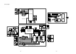
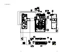
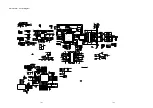
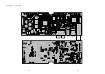
Power Board -- Circuit Diagram 2
12-9
12-9
Summary of Contents for MCM7000/12
Page 30: ...AMP BOARD Layout Diagram 12 2 12 2 ...
Page 32: ...Display Board Layout Diagram 12 4 12 4 ...
Page 35: ...Key Board Layout Diagram 12 7 12 7 ...
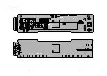
Page 38: ...T5AH 250V Power Board Layout Diagram 12 10 12 10 ...
Page 42: ...Decoder Board Layout Diagram 12 14 12 14 ...
Page 44: ...Revision List Revision List Version 1 0 Initial Release 14 1 ...


