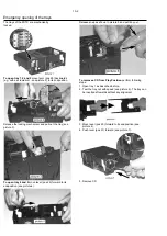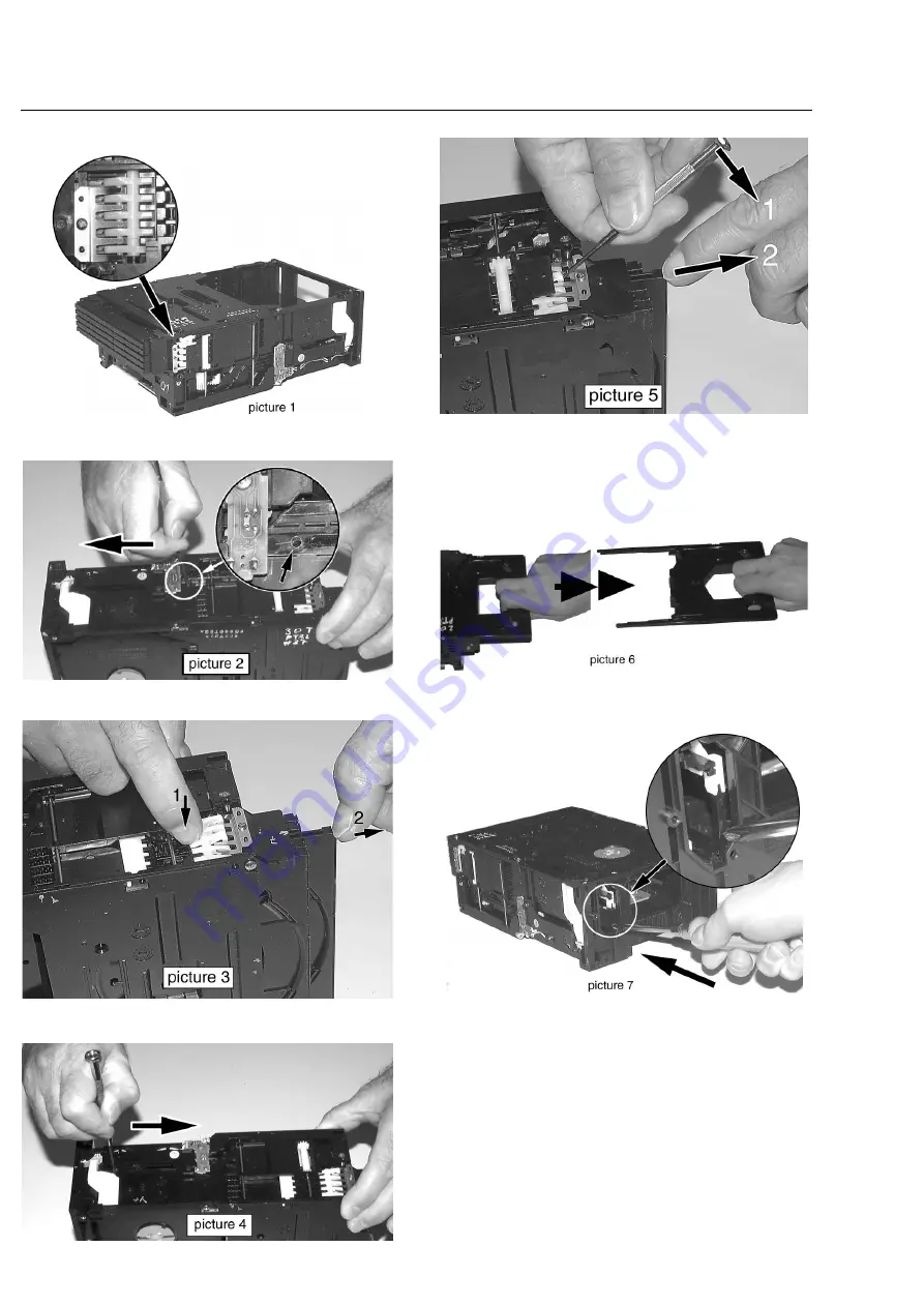
The trays of the 5DTC are mechanically
locked.
To open tray 1, 2 and 3 move lever (pos 29) backwards
(e.g. with a screwdriver - see picture 2) to its endposition.
Release the locking mechanism and pull out the tray (see
picture 3).
To open tray 4 and 5 move lever (pos 29) forward to its
endposition (see picture 4).
Release snap as shown in picture 5 and pull tray out.
To remove a CD from Play Position perform following
steps:
1. Open tray 1 as described before.
2. Tear the tray out with speed (see picture 6). The tray can
be inserted aftewards without any alignment.
3. Move lever (pos 29) forward to its endposition (see
picture 4).
4. Push lever (pos 31) forward (see picture 7).
5. Remove CD.
10-2
Emergency opening of the trays
Summary of Contents for MX5800SA
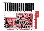
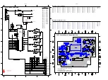
Page 68: ...8239 210 93416 3139 113 3494pt6 dd wk0334 PART B 8 13 8 13 SUPPLY BOARD CHIP LAYOUT PART B ...
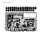
Page 76: ...3104 213 3525p5 dd wk0334 PART B 8 19 8 19 AMPLIFIER BOARD BOTTOM VIEW PART B ...
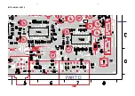
Page 78: ...3104 213 3525p5 dd wk0334 PART D 8 21 8 21 AMPLIFIER BOARD TOP VIEW PART D ...
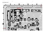
Page 91: ...9 10 9 10 BOTTOM VIEW PART C PART C ...
Page 92: ...9 11 9 11 BOTTOM VIEW PART D PART D 3139 113 3500 pt6 dd wk334 ...
Page 95: ...9 14 9 14 BOTTOM VIEW PART G PART G ...
Page 96: ...9 15 9 15 BOTTOM VIEW PART H PART H 3139 113 3500 pt6 dd wk334 ...
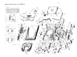
Page 104: ...10 5 10 5 Exploded view 5DTC mechanic for orientation only ...
Page 111: ...BOTTOM VIEW COMPONENT LAYOUT For pcb layout 35037 11 4a 11 4a 3139 113 3503 pt 7 dd wk414 ...
Page 112: ...TOP VIEW PART A 11 5 11 5 PART A ...
Page 113: ...TOP VIEW PART B 11 6 11 6 PART B ...
Page 115: ...TOP VIEW PART B For pcb layout 35037 11 6a 11 6a 3139 113 3503 pt 7 dd wk414 PART B ...
Page 126: ...12 1 12 1 EXPLODED VIEW MAIN UNIT MX5800SA exploded view 3139 119 35170 dd wk318 ...

