5
5
4
4
3
3
2
2
1
1
D
D
C
C
B
B
A
A
+15V
-12V
Panel Gate Driver Power
Vdc
Vdc
BJT Amplifier for T-CON I/F
Vdc
89P VCOM DAC OUTPUT
VCOM DAC OP POWER
25
6
23
GND
STHL
10
GND
SOE
VGH
MOD
GOE
9
CPH2
CLK
VCOM
19
3
20
VR
11
4
26
U/D
STVR
22
24
1
L/R
16
VGL
7
17
AVDD
13
STVL
Bottom Socket
8
VB
21
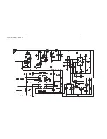
LG&PHILIPS LT070W02
STHR
15
AVSS
VG
CPH1
2
14
18
7" PANEL
CPH3
5
VCOM
12
VCC
VCC
!
D
1
1
Wednesday, May 21, 2008
Title
r
e
b
m
u
N
t
n
e
m
u
c
o
D
e
z
i
S
t
e
e
h
S
:
e
t
a
D
of
5V
OEH
TFT_B
BL_EN
5V
+9V
OEV
TFT_R
CKV
TFT_G
89KP_VCOM
STVL
BOUT
UND
LNR
TFT_R
ROUT
GOUT
TFT_B
TFT_G
5V
89KP_VCOM
-6V_VOP
VGH
5V
CPH1
MOD
BOUT
STVL
UND
CPH2
LNR
GOUT
ROUT
STHR
VGH
VCOM
VCOM
VCOM
VCOM
CPH1
CKV
OEH
VGL
OEV
STHL
STVR
STHL
CPH3
VCOM
BL_EN
VGL
V_BIAS
V_BIAS
AMP_VDD
AMP_VDD
AMP_VDD
V_BIAS
AMP_VDD
V_BIAS
5V
5V
-12V_VOP
5V
-6V_VOP
5V
5V
+5V
+9V
+5V
AR7
1K
1
2
AR8
2.2K
1
2
AR43
1M
AR51
7K5
RT21
100K NTC 1%
1
2
AC6
2200P
AR32
10R
RH18
470
1
2
AC28 1uF/0805
AQ1
3906
3
2
1
AR6
1K
1
2
AC29
0.1uF
AQ6
2N3904
2
1
3
AR34
0
AR59
13K
AR52
20k
AC15
0.1uF
+
AE1
10uF/16V(A)
AR56
75/1%
AC19
1uF
AR58
10/0805
1
2
AC20 1uF/0805
AR26
22K
1
2
AR49
270
AR42
1M
AR29
2K
J2
DIP11/1.25/HORIZONTAL
1
2
3
4
5
6
7
8
9
10
11
STVL
GNDA
CKV
OEV
GNDB
OEH
STHL
GNDC
CPH1
GNDD
VCOM
AC4
0.1uF
HV+
AC31 1uF/0805
AT1
TRANSFORMER DC-AC CI-8.5 (SKT)
7
5
6
4
3
2
1
AC9
0.1uF
AR54
20K
AC2
2.2uF
AC18 1uF
AS1
VR-10K
1
3
2
AC22
10pF
+
AC40
10uF/10V/0805
AE2
10uF/16V(A)
1
2
AR22
10R
1
2
AD1
SSD03
1
2
AD2
5.6V
1
2
AQ4
2N3904
2
1
3
+
AC39
10uF/10V/0805
AR41
1M
AR23
100R
1
2
AR1
1K
1
2
AR61
75K
AC8
0.1uF
AC27 1uF/0805
AC41
10uF/10V/0805
AR15
470R
1
2
AR35
100K
AC37
10uF/25V/1206
1
2
AC16
0.1uF
L1
22uH
AC1
0.1uF
AC5
0.1uF
AU3
SS6608
1
2
3
4
5
1
2
3
4
5
AR46
75/1%
+
AE6
10uF/16V(A)
AC3
4700P
AC13
0.1uF
AC25
0.1uF
AR19
4.7K
1
2
AR48
20k
AQ9 SS214U
1
2
3
AC35
10uF/25V/1206
1
2
AR65
20K
AR57
270
AU1
SS7707
1
2
3
4
5
6
7
8
9
10
11
12
13
14
15
16
REF
REF1
FB1
NC
REF2
FB2
TFB
ATC
CT
RT
GND
V-D
B-D
A-D
V-D
VCC
AR36
OR
AR10
4.7K
1
2
AC10
0.1uF
AR14
1K
1
2
AR12
4K7
1
2
+
AC38
10uF/10V/0805
+
AC36
10uF/10V/0805
AQ3
2N3904
2
1
3
AC7
0.1uF
RH7
330K
1
2
AC14
0.1uF
AD4
7V5
1
2
AR9
15K
1
2
AE5
10uF/16V(A)
+
-
AU2A
CSC3414A DMP8 HWCAT
3
2
1
8
4
AJ4
WAFER 4PIN 1.25mm SMD LEVEL
1
2
3
4
GNDA
R
B
G
RH19
22K
1
2
AR44
1M
AR40
1M
AQ5
2N3904
2
1
3
AR53
270
AR28
1K
AR39
10K
AC34
10uF/25V/1206
1
2
RH12
33K
1
2
AC26 1uF/0805
AC33
2.2uF/25V
AR45
1M
HV-
AC11
0.1uF
AR17
100R
1
2
AU5
STM4532
1
2
3
4
5
6
7
8
AU4
STM4532
1
2
3
4
5
6
7
8
AE4
100uF/16V/SMD
AR33
39k
AC12
0.1uF
AR21
10R
1
2
AQ8 SS214U
1
2
3
HA3
26PSMD0.5MM
26
25
24
23
22
21
20
19
18
17
16
15
14
13
12
11
10
09
08
07
06
05
04
03
02
01
AVSS
AVDD
VB
VG
VR
GND
VCC
CPH1
CPH2
CPH3
STHR
STHL
OEH
MOD
LR
VCOM
VCOM
OEV
U/D
CKV
STVL
STVR
VGH
VGL
VCC
GND
AC17
0.01uF
AR50
75/1%
+
-
AU2B
NJM4556OPA
5
6
7
8
4
AC30 1uF/0805
AR31
100
AC23
0.1uF
AQ2 3906
3
2
1
AR25
22K
1
2
AQ7
2N3904
2
1
3
AR20
4.7K 1%
1
2
AR18
1K
1
2
AR24
100R
1
2
AR11
10K
1
2
J3
DIP5/1.25/HORIZONTAL
1
2
3
4
5
+9V
VGND
+5V
GND
B_EN
AR60
10R
AC32 1uF/0805
AQ8 SS214U
1
2
3
AL1
100uH
1
2
AD3
5.6V
1
2
AC24
0.1uF
AQ11
SS214U
1
2
3
AL3
FB600R
AR13
100K
1
2
AR16
10K
1
2
AC21
0.1uF
AL2
FB600R
AR47
7K5
AR55
7K5
AR30
10K
AR38
10K
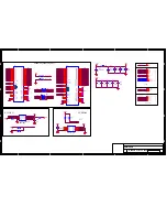
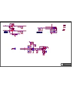
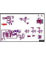
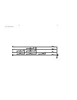
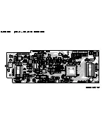
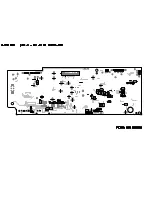
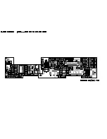
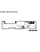
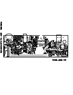
PET816 TFT
Summary of Contents for PET816/05
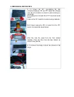
Page 9: ...3 0 INSTRUCTION FOR USE ...
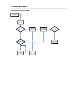
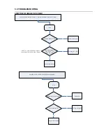
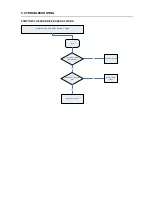
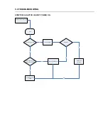
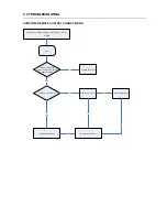
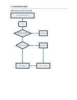
Page 18: ...5 0 TROUBLESHOOTING SYMPTOM NO SOUND FROM HEADPHONE ...
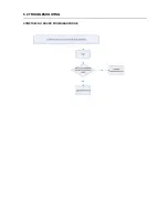
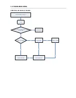
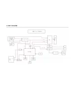
Page 21: ...6 0 BLOCK DIAGRAM ...
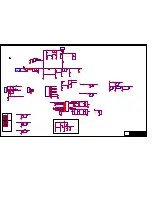
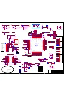
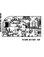
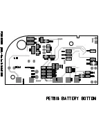
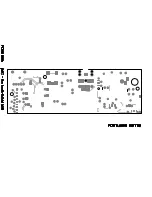
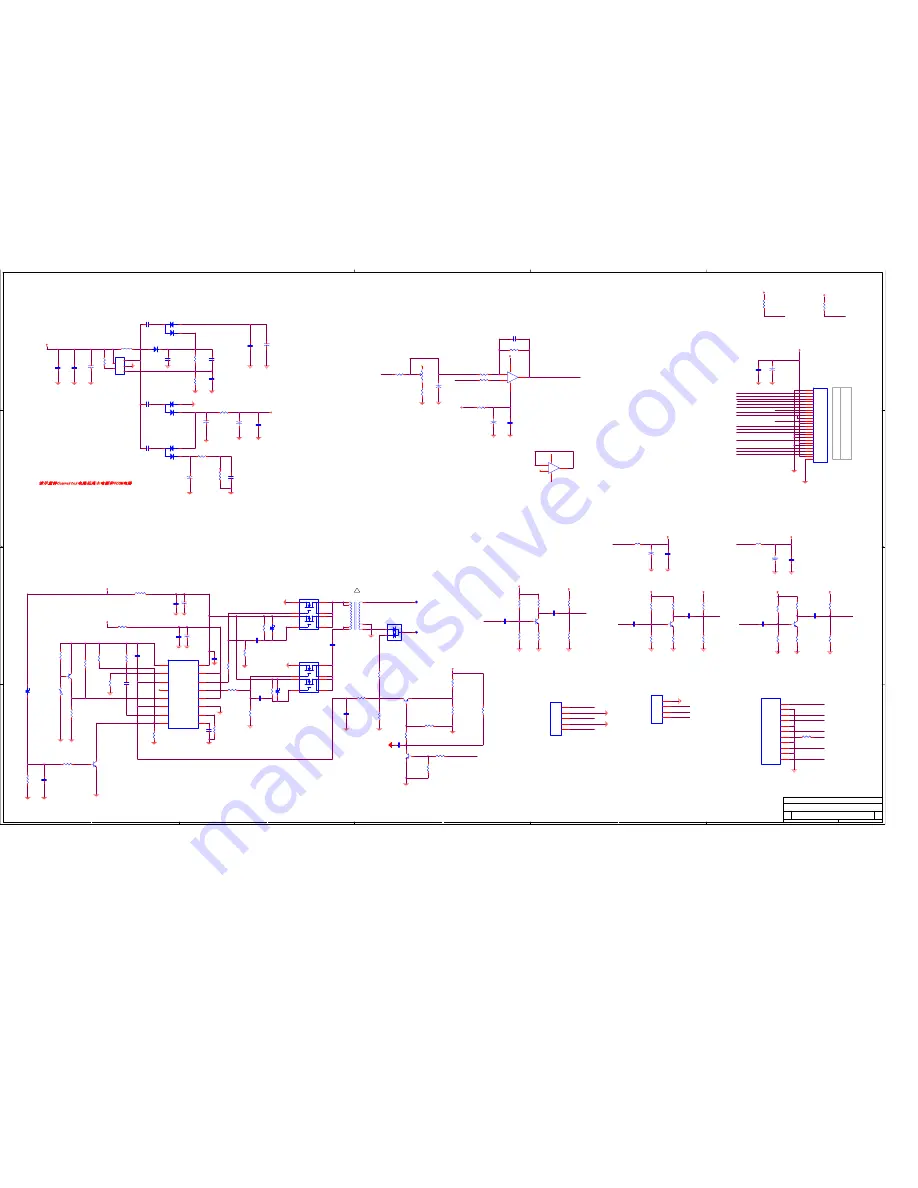
Page 28: ...CIRCUIT DIAGRAM BATTERY 1 1 1 1 ...
Page 29: ......
Page 30: ......
Page 31: ......
Page 32: ......
Page 33: ......
Page 34: ......
Page 35: ......
Page 36: ......


