background image

J8 CHASSIS SERVICE ADJUSTMENTS

Service Adjustment Notes:

REQUIRED TOOLS FOR SERVICING

Isolation Transformer
Multimeter
Oscilloscope
High Voltage (100:1) Oscilloscope Probe
Sencore VG91 Universal Video Generator

Caution:  The J8 chassis incorporates a "hot" ground system. Always use a separate isolation

transformer when applying power to the exposed chassis.

Unless Otherwise Specified:
1.  All service adjustments are "hot" voltagewise. For maximum safety, ensure the use of properly

insulated tools.

2.  Refer to the J8 Main Chassis Printed Circuit Board for location of test points and adjustable

components.

3.  Grid Locations (Ex.: D-3) next to the reference numbers for components refer to the Main Chassis

Printed Circuit Board.

Focus Adjustment

1.  Tune the set to a local or cable station.
2.  Adjust the Focus Control (located on the upper part of the flyback transformer) for best picture details

at high light conditions.

Degaussing the Television
1.  Position the television so that the screen faces the direction it will be facing when in use.
2.  Ensure the set is turned off.
3.  Move a degaussing coil in a circular motion slowly around the sides and front of the set.
4.  Continue this motion while withdrawing the degaussing coil at least six feet from the television, and

then disconnect the degaussing coil from its power source.

Service mode

Introduction

The service mode is a combined Service Default Mode (SDM) and Service Alignment Mode (SAM). This
service mode is Called SDAM. When the television is in SDAM, all normal features (such as volume
control and direct channel access) are available. In service mode there will be an "S" displayed (in green)
at the top right of the screen. All other Service OSD’s will also be in green.

Error buffer

Error codes will indicate failures in the television.
A unique error code is available for:

•    

activated protection

•    

failing I2C device

•    

general I2C error

•    

RAM failure (e.g. internal RAM of microprocessor)    

Summary of Contents for PR1906C121

Page 1: ...ual 7590 Model no PR1906C121 First Publish 10 09 01 Rev Date 04 04 00 Print Date 18 07 2006 Pg SCHEMATIC DIAGRAMS AND PC BOARDS 1 Schematic Circuitry Listings 2 Main Ch Power Supply Circuitry A01 3 Main Ch Line Deflection Circuitry A02 4 Main Ch Frame Deflection Circuitry A03 5 Main Ch Sync Circuitry A04 6 Main Ch Tuner Video IF Circuitry A05 7 Main Ch Video Processing Circuitry A06 8 Main Ch SIF ...

Page 2: ...LIARIZE HIMSELF WITH THE CHASSIS AND BE AWARE OF THE NECESSARY SAFETY PRECAUTIONS TO BE USED WHEN SERVICING ELECTRONIC EQUIPMENT CONTAINING HIGH VOLTAGES CAUTION USE A SEPARATE ISOLATION TRANSFORMER FOR THIS UNIT WHEN SERVICING Philips Electronics North America Corporation Visit our World Wide Web Site at http www forceonline com Manual 7590 Model no PR1906C121 First Publish 10 09 01 Rev Date 04 0...

Page 3: ...MAIN CABINET EXPLODED VIEW Page 1 of 1 ...

Page 4: ...MILIARIZE HIMSELF WITH THE CHASSIS AND BE AWARE OF THE NECESSARY SAFETY PRECAUTIONS TO BE USED WHEN SERVICING ELECTRONIC EQUIPMENT CONTAINING HIGH VOLTAGES CAUTION USE A SEPARATE ISOLATION TRANSFORMER FOR THIS UNIT WHEN SERVICING Philips Electronics North America Corporation Visit our World Wide Web Site at http www forceonline com Manual 7590 Model no PR1906C121 First Publish 10 09 01 Rev Date 04...

Page 5: ......

Page 6: ......

Page 7: ......

Page 8: ......

Page 9: ......

Page 10: ......

Page 11: ......

Page 12: ......

Page 13: ......

Page 14: ...LIARIZE HIMSELF WITH THE CHASSIS AND BE AWARE OF THE NECESSARY SAFETY PRECAUTIONS TO BE USED WHEN SERVICING ELECTRONIC EQUIPMENT CONTAINING HIGH VOLTAGES CAUTION USE A SEPARATE ISOLATION TRANSFORMER FOR THIS UNIT WHEN SERVICING Philips Electronics North America Corporation Visit our World Wide Web Site at http www forceonline com Manual 7590 Model no PR1906C121 First Publish 10 09 01 Rev Date 04 0...

Page 15: ...8 chassis the necessary electrical information should be covered in this service manual even if the corresponding model number is not listed PHILIPS MAGNAVOX MODELS Model Size Panel Number Description 13PR20C1 13 00EMJ800 Main Chassis PR1306C1 13 00EMJ801 Main Chassis PR1320C1 13 00EMJ800 Main Chassis PR1392X1 13 00EMJ802 Main Chassis 19PR21C1 19 00EMJ803 Main Chassis 19PR21C2 19 00EMJ803 Main Cha...

Page 16: ...rightness Color Picture Sharpness Tint Contrast Plus SOUND POWER OUTPUTS Stereo 2 x 1 Watts Mono 1 Watt SPEAKERS Types 3 round 16 Ohm 4W 8 Ohm 2W SOUND CONTROLS Volume 64 steps Mute on off AVL on off SOUND MUTE When there is no video recognition on terrestrial tuner signal the sound will be muted POWER SUPPLY SPECIFICATIONS PERFORMANCE Mains voltage range 120 10 Mains frequency 60 Hz Chassis mains...

Page 17: ... Output 8 4 mW 600 4 mW Sound is the same as from the loudspeakers ESD protected 4 kV Signal Remote Cross Reference Model Part Number Description 13PR20C121 3139 228 83601 Remote Transmitter RC1112901 04 19PR21C121 C122 C125 C222 3139 228 83601 Remote Transmitter RC1112901 04 19PS57C121 C125 3139 228 83601 Remote Transmitter RC1112901 04 PR1306C121 3139 228 83591 Remote Transmitter RC1112501 04 PR...

Page 18: ...ernal audio video input FM Frequency Modulation I F Intermediate Frequency I C Inter IC bus 2 wire bi directional SCL SDA ID Identification IDENT Horizontal coincidence signal transmitter identification IF Intermediate Frequency IN ITT sound IC with NICAM function IT ITT sound IC without NICAM function LATAM Latin America LED Light Emitting Diode Local Keyboard The buttons usually volume up volume...

Page 19: ...ns of the line output transformer LOT flyback capacitor s S correction capacitor s line output transistor pins of the connector with wires to the deflection coil other components through which the deflection current flows Resolder points are marked by a white circle on the bottom of the CBA The wire trees and EHT cable should be routed correctly and fixed with the mounted cable clamps The insulati...

Page 20: ...Note After servicing this unit be sure to check that the AC cord is properly dressed as shown in the detailed view Display AC Cord Lead Dress ...

Page 21: ...Display Feature Chart ...

Page 22: ...Display RC1112501 Remote ...

Page 23: ...Display RC1112901 Remote ...

Page 24: ...Display RC282901 Remote ...

Page 25: ...Display Jack Panel Information Chart ...

Page 26: ......

Page 27: ......

Page 28: ...IARIZE HIMSELF WITH THE CHASSIS AND BE AWARE OF THE NECESSARY SAFETY PRECAUTIONS TO BE USED WHEN SERVICING ELECTRONIC EQUIPMENT CONTAINING HIGH VOLTAGES CAUTION USE A SEPARATE ISOLATION TRANSFORMER FOR THIS UNIT WHEN SERVICING Philips Electronics North America Corporation Visit our World Wide Web Site at http www forceonline com Manual 7590 Model no PR1906C121 First Publish 10 09 01 Rev Date 04 04...

Page 29: ...for best picture details at high light conditions Degaussing the Television 1 Position the television so that the screen faces the direction it will be facing when in use 2 Ensure the set is turned off 3 Move a degaussing coil in a circular motion slowly around the sides and front of the set 4 Continue this motion while withdrawing the degaussing coil at least six feet from the television and then...

Page 30: ...ro 7600 low and shut off TV A one 1 will be stored after the fault is cleared 2 I2C error while communicating with a processor 3 General I2C error 4 Internal RAM error micro controller 5 I2C error EEPROM error 6 I2C error PLL tuner 7 Stereo I2C error Note I2C SCL SDA General I2C error means no I2C device is responding to the particular I2C bus Possible causes SCL Short circuit to GND SDA Short Cir...

Page 31: ...he set can be performed From the Virtual Customer Mode press the Menu button to return to the SDAM display 7 To exit the Service Default Alignment Mode and erase the error codes turn the unit off with the Power button on the remote control then unplug the ac cord 8 To exit the Service Default Alignment Mode and save the error codes unplug the ac cord to turn off the set Turn the set back on the Se...

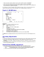
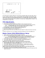
Page 32: ...n number 1 0 S The character S to indicate that the TV set is in service mode SDAM The ERR Error row displays the last five errors detected the most recent error will be displayed to the left Geometry Adjustments Notes 1 The following Geometry adjustments were performed with a Sencore VG91 Universal Video Generator 2 Set the VG91 Generator as follows STD TV Ch 3 RF IF Range set to HI RF IF Level s...

Page 33: ...oceed to the necessary adjustment using the Menu Up Down buttons Horizontal Phase H PH Note This adjustment centers the video on the raster It does not move the raster 1 Enter the Service Default Alignment Mode SDAM in either of the following two ways a Press the following key sequence on the remote control transmitter while the set is in Standby mode 0 6 2 5 9 6 Status Do not let the sequence tim...

Page 34: ...ction is on the stereo is enabled Tuner Adjustment AGC Takeover Point AGC 1 Enter the Service Default Alignment Mode SDAM in either of the following two ways a Press the following key sequence on the remote control transmitter while the set is in Standby mode 0 6 2 5 9 6 Status Do not let the sequence time out between entries b Short service pin 0239 on the CBA to ground and switch power on 2 Use ...

Page 35: ...ress Menu to return to the SDAM menu Master Screen VG2 White Balance Setup 1 Apply a center cross pattern to the antenna cable input terminal 2 Enter the Service Default Alignment Mode SDAM in either of the following two ways a Press the following key sequence on the remote control transmitter while the set is in Standby mode 0 6 2 5 9 6 Status Do not let the sequence time out between entries b Sh...

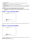
Page 36: ...rightest bar white 18 Adjust the CO as needed to touch up low light areas to make the darkest bar grey NOTE The Color Drivers set the highlights and the Cut offs set the lowlights Also these items interact A Decrease of the Red Drive may require an increase of teh Red Cut off etc Figure 5 Color Cutoff Sub Menu The CO Color Cutoff sub menu consists of Red R Blue B and Green G cutoff values range fr...

Page 37: ...sequence on the remote control transmitter while the set is in Standby mode 0 6 2 5 9 6 Status Do not let the sequence time out between entries b Short service pin 0239 on the CBA to ground and switch power on 3 Apply a center cross or crosshatch pattern to the antenna cable input terminal 4 From the SDAM menu use the Menu Up Down buttons to highlight CO Color Cut off 5 Use the Menu Right button t...

Page 38: ...2YPOLE 2X POLE 4 POLE 6 POLE ZERO CORRECT ION POSIT ION CONVERGENCE PURIT Y ASSEMBLY GAP GRIDS G2 G3 Figure 8 2X 2Y Spread Rotate ...

Page 39: ... the Menu Left button to set Blue to minimum 6 Use the Menu Up Down buttons to select Red and use the Menu Right button to set Red to maximum 7 Slowly spread the 2 X pole purity rings to center the red portion of the screen leaving the same amount of green on one side of the screen as blue on the other side 8 Tighten the yoke clamp screw slightly so that the yoke may be moved with some friction 9 ...

Page 40: ...the Menu Left button to set Green to minimum 3 Tilt the yoke up and down to converge the red and blue vertical lines at the 6 00 and 12 00 positions and the red and blue horizontal lines at the 3 00 and 9 00 positions refer to Figure 11 When the correct position has been found place a rubber wedge between the yoke and the CRT If the yoke is tilted up place wedge one as shown in Figure 9a if it is ...

Page 41: ...Fig 9a Fig 9b Fig 9c Fig 10a Fig 10b Fig 10c Figures 11 12 Yoke Tilt ...

Page 42: ...Figure 11 Figure 12 ...

Page 43: ...Display Figure 1 SDAM Flow Chart ...

Page 44: ...LIARIZE HIMSELF WITH THE CHASSIS AND BE AWARE OF THE NECESSARY SAFETY PRECAUTIONS TO BE USED WHEN SERVICING ELECTRONIC EQUIPMENT CONTAINING HIGH VOLTAGES CAUTION USE A SEPARATE ISOLATION TRANSFORMER FOR THIS UNIT WHEN SERVICING Philips Electronics North America Corporation Visit our World Wide Web Site at http www forceonline com Manual 7590 Model no PR1906C121 First Publish 10 09 01 Rev Date 04 0...

Page 45: ......

Page 46: ... FAMILIARIZE HIMSELF WITH THE CHASSIS AND BE AWARE OF THE NECESSARY SAFETY PRECAUTIONS TO BE USED WHEN SERVICING ELECTRONIC EQUIPMENT CONTAINING HIGH VOLTAGES CAUTION USE A SEPARATE ISOLATION TRANSFORMER FOR THIS UNIT WHEN SERVICING Philips Electronics North America Corporation Visit our World Wide Web Site at http www forceonline com Manual 7590 Model no PR1906C121 First Publish 10 09 01 Rev Date...

Page 47: ... 01090 2606 10pF 5 50V Ceramic 3198 016 01090 2607 10pF 5 50V Ceramic 3198 016 01090 2608 1uF 16V Ceramic 3198 017 21050 2609 0 01uF 10 50V Ceramic 3198 017 01030 2610 470uF 10V Electrolytic 3198 025 14710 2613 220pF 5 50V Ceramic 3198 016 02210 2614 1uF 20 50V Electrolytic 3198 025 51080 2615 1000pF 5 50V Ceramic 3198 016 01020 2616 1000pF 5 50V Ceramic 3198 016 01020 2617 470pF 5 50V Ceramic 319...

Page 48: ... 30483 3755 33k 1 4W Carbon Film 4835 110 57375 3756 22 ohm 0 6W Metal Film 4835 116 57765 3757 Zero ohm 4835 111 27056 3759 2 2 ohm 5 1 6W Carbon Film 3198 011 02280 3760 470 ohm 5 1 10W Metal Film 4835 111 37259 3761 2 7k 5 1 10W Metal Film 3198 021 52720 3762 22 ohm 0 6W Metal Film 4835 116 57765 S 3763 1 5k 3W Metal Oxide 2120 105 93457 3801 33k 5 1 10W Metal Film 4835 111 37248 3802 27k 5 1 1...

Page 49: ...AC09 Light Guide 3139 124 31921 AC11 Speaker 25 ohm 1 5W 2422 264 00336 AC13 Chassis Guide 3139 124 32951 AC15 Speaker Clip 3139 124 32931 REMOTE Remote Transmitter RC1112501 04 3139 228 83591 AC17 Battery AA 1 5V 2pk 9299 000 10137 AC18 Owner s Manual 3135 015 18291 AC19 Instruction Sheet 3135 015 16771 CRT Panel Parts CRT Panel Parts 0165 1 Pin Board Connector 3104 301 09521 0244 3 Pin Board Con...

Reviews: