−
if the main version number changes, the new version number is written in the EEPROM.
−
if the sub version number changes, the new version number is written in the EEPROM.
−
Note: a new micro controller is considered to be compatible if it works instead of the old software and
the functionality is not significantly changed.
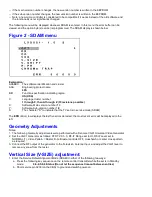
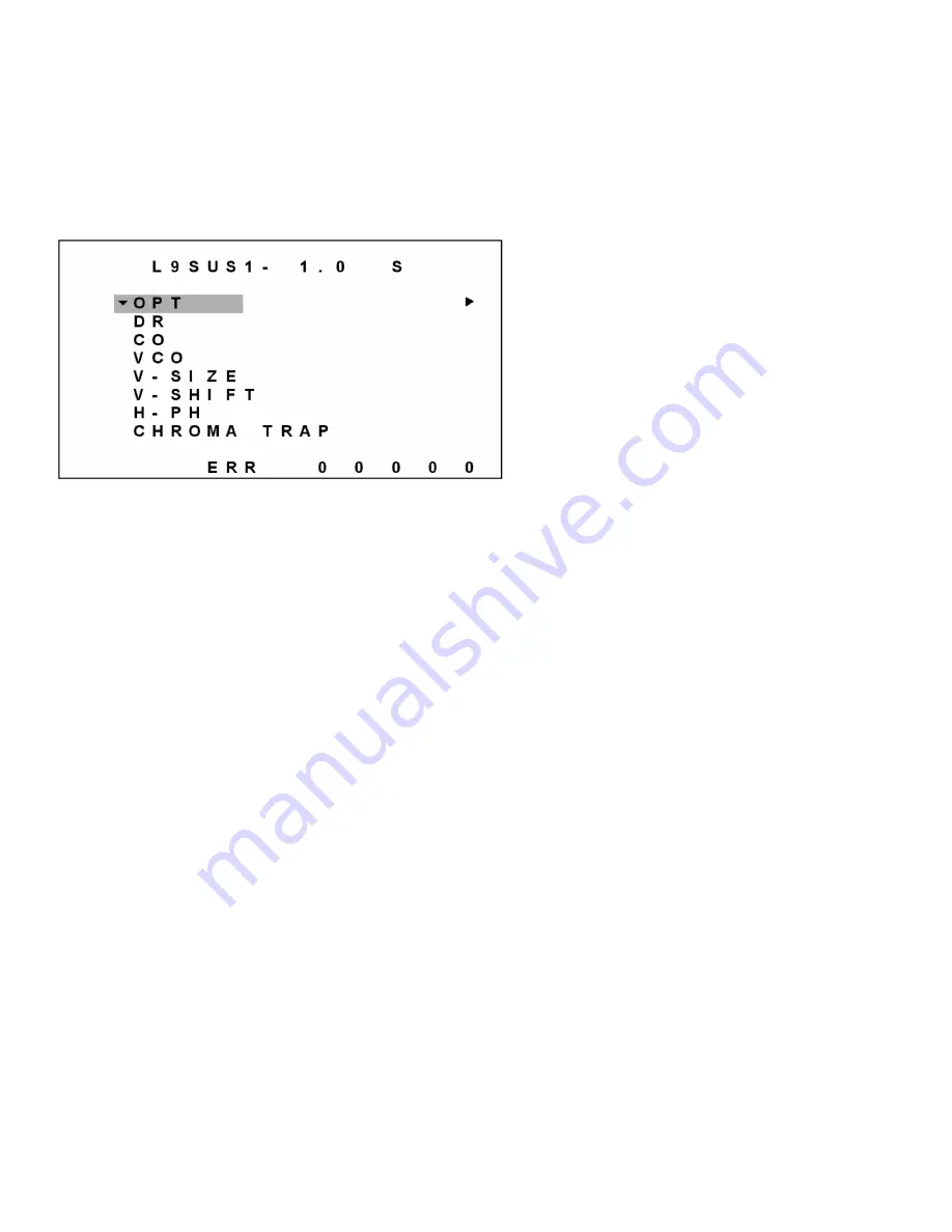
The following menu will be displayed whenever SDAM is entered. In this menu the error buffer can be
viewed, and the option byte(s) can be (re)programmed. The SDAM display is shown below:
Figure 2 - SDAM menu
Explanation:
AAABBC
The software identification and cluster
AAA:
Engineering project name.
L9S
BB:
Function specification indicating region.
US (USA)
C:
Language cluster number:
1 through 9, then A through Z (35 revisions possible)
X:
Software, Main version number 1.0
Y:
Software, Sub-version number 1.0
S
The character "S" to indicate that the TV set is in service mode (SDAM).
The ERR (Error) row displays the last five errors detected; the most recent error will be displayed to the
left.
Geometry Adjustments
Notes:
1. The following Geometry adjustments were performed with a Sencore VG91 Universal Video Generator.
2. Set the VG91 Generator as follows: STD TV Ch. 3, RF-IF Range set to HI, RF-IF Level set to
NORMAL (1), Video Pattern = Raster, R-G-B raster controls OFF, crosshatch or center cross pattern
as required.
3. Connect the RF output of the generator to the Television Antenna Input, and adjust the VG91 level to
remove any snow from the raster.
Vertical Size (V-SIZE) adjustment:
1. Enter the Service Default Alignment Mode (SDAM) in either of the following two ways:
a. Press the following key sequence on the remote control transmitter while the set is in Standby
mode: 0-6-2-5-9-6-Status (Do not let the sequence time-out between entries)
b. Short service pin 0239 (on the CBA) to ground and switch power-on.
Summary of Contents for PR1906C121
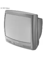
Page 3: ...MAIN CABINET EXPLODED VIEW Page 1 of 1 ...
Page 5: ......
Page 6: ......
Page 7: ......
Page 8: ......
Page 9: ......
Page 10: ......
Page 11: ......
Page 12: ......
Page 13: ......
Page 21: ...Display Feature Chart ...
Page 22: ...Display RC1112501 Remote ...
Page 23: ...Display RC1112901 Remote ...
Page 24: ...Display RC282901 Remote ...
Page 25: ...Display Jack Panel Information Chart ...
Page 26: ......
Page 27: ......
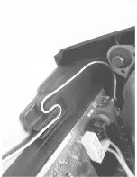
Page 41: ...Fig 9a Fig 9b Fig 9c Fig 10a Fig 10b Fig 10c Figures 11 12 Yoke Tilt ...
Page 42: ...Figure 11 Figure 12 ...
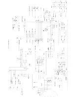
Page 43: ...Display Figure 1 SDAM Flow Chart ...
Page 45: ......


