13. Turn the set back off.
14. Adjust G2 (Screen) clockwise until a line just becomes visible. This line will be the color of the
dominant gun.
15. Adjust the other two cutoff controls to achieve a low level white line.
16. Apply a NTSC color bar signal with Chroma turnedoff. Tr-enter SDAM (see #2) and select the needed
sub menu as follows:
17. Make slight adjustments, if necessary, to the Red and Blue Drive controls to make the brightest bar
white.
18. Adjust the CO as needed, to touch up low light areas to make the darkest bar grey.
NOTE: The Color Drivers set the highlights and the Cut offs set the lowlights.
Also, these items interact. A Decrease of the Red Drive may require an increase of teh Red
Cut off, etc.
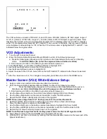
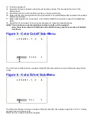
Figure 5 - Color Cutoff Sub-Menu
The CO (Color Cutoff) sub-menu consists of Red (R), Blue (B) and Green (G) cutoff values range from 0
to 255.
Figure 6 - Color Driver Sub-Menu
The DR (Color Drivers) sub-menu consists of Red (R), Blue (B) drive values range from 0 to 127. Factory
preset for the color drivers is 63.
Note: There is no Green color Drive register.
Summary of Contents for PR1906C121
Page 3: ...MAIN CABINET EXPLODED VIEW Page 1 of 1 ...
Page 5: ......
Page 6: ......
Page 7: ......
Page 8: ......
Page 9: ......
Page 10: ......
Page 11: ......
Page 12: ......
Page 13: ......
Page 21: ...Display Feature Chart ...
Page 22: ...Display RC1112501 Remote ...
Page 23: ...Display RC1112901 Remote ...
Page 24: ...Display RC282901 Remote ...
Page 25: ...Display Jack Panel Information Chart ...
Page 26: ......
Page 27: ......
Page 41: ...Fig 9a Fig 9b Fig 9c Fig 10a Fig 10b Fig 10c Figures 11 12 Yoke Tilt ...
Page 42: ...Figure 11 Figure 12 ...
Page 43: ...Display Figure 1 SDAM Flow Chart ...
Page 45: ......


