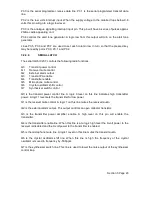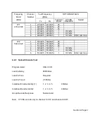
4.5.5 VHF Receiver Front End Alignment
(Continued)
Step
No
Result
Measured by
Result
Measured at
Adjust
Result
Notes
15
RF sig. gen.
output.
0.31 uV pd
level.
16
SINAD
meter
Speaker
output at
SK202.
Greater
than 12dB
SINAD.
Verifies alignment
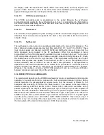
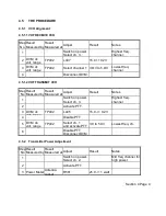
4.5.6 Mute Maximum Alignment
Step
No
Result
Measured by
Result
Measured at
Adjust
Result
Notes
1
Switch on power
select channel 2.
Mid freq. channel.
2
Antenna
socket SK402
RF sig. gen.
output.
Freq. of ch. 2,
1 mV pd level
Modulate generator
with 1 kHz at 60% of
max dev.
3
AF level
meter.
Speaker
output SK202
Volume
control.
300mW in 4ohm.
4
Sinad meter
Speaker
output SK202
RF sig. gen.
output level
a) 23dB SINAD
b) 19 +/- 1dB
SINAD
a) for 20/25/30 kHz
channel spacing
b) for 12.5kHz
channel spacing
Record sig. gen. level.
5
Switch off RF
sig. gen. output.
6
Speaker
output SK202
Mute control
fully clock-wise.
AF should mute
If AF does not mute,
adjust R455
7
Switch on RF
sig. gen.
Same output
level as in step 4.
Ensure AF is
muted.
If AF does not mute,
adjust R455 slightly
clockwise to achieve
result.
8
AF level
meter.
Speaker
output SK202
R455 slowly
counter-clockwise.
AF output Adjust R455 carefully
appears.
9
AF level
meter.
Speaker
output SK202
RF sig. gen.
output off.
AF should mute If AF does not mute
R455 has incorrect
adjustment.
Repeat steps 4 to 8.
10
AF level
meter.
Speaker
output SK202
RF sig. gen.
output on.
AF should If AF does not
unmute. carefully re-adjust
R455
Section 4 Page 8


