background image

4 -  3

4 - 3

3519 B6

3524 C7

7511 C7

F514 D6

6

2527 C2

3557 B5
3558 C5

6502 C10

*

C

2503 B7

3521 B4

1,3V

3522 B3

2531 D7
2532 D8

2533 D6
2534 D7

X

X

F515 E7

3526 C6
3530 C8
3534 C3

2524 C9

2526 C8

2525 C4

2522 B9

*

2523 C5

7

3553 D8

2528 C1

3554 D8
3555 D7

3551 D4

3556 E8

3552 D6

2516 B2

D

2520 B5

F505 B10

3559 A6
3560 B10

2511 B2

D

2502 B6

C

B

2515 B1

B

2537 A7

2538 A7
3500 A5
3501 A4
3502 A5
3503 A8

3505 B5
3506 B6

6503 D5

7500-A D7
7500-B A7
7501 B9
7503 B3
7506 B6

7508 B4
7510 B7

3518 C3

F508 C7
F510 C10

3525 C4

3547 C5
3548 D5

3535 C6

3539 C4
3542 C8
3543 C1
3544 C1
3545 C9

3546 C5

10

1

2

3

4

5

6

7

3507 B8
3508 B8
3510 B1

3511 B1
3513 B3
3514 B4
3515 B7
3517 B9

A

7513 C9

7515 E7
F501 B6
F502 B2
F503 B9
F504 B10

4001 B9

4002 D9
6500 B8
6501 C9

2530 C10

2529 C2

2535 E8
2536 C5

E

680R

8

9

10

A

E

1500 C10
2500 A7
2501 B8

F506 B4

F513 C9

F511 C9
F512 C2

1

2

3

4

5

F507 B6

3549 D8

7512 C4

8

9

3510

2500

10K

3554

330R

3517

A

330p

BC817-40

A

A

7512

2u2

2533

4K7

3500

100K

3521

A

F502

7503

BC857B

BC847B

7511

7513
BC817-40

15R

3503

BC817-40
7501

6.3V

220u

2538

3511

A

A

680R

7515
BC847B

12K

3501

2515

2n2

3502

2M2

330p

2531

A

2511

4u7

35V

3559

10R

F510

2530

1u0

F504

F505

F513

F511

F503

F515

F506

F508

F501

F514

BAV70

6500

4V 220u

2532

680R

3544

100n

2523

2520

100n

2502

2u2

2516

1n5

18K

3526

4V

2536

47u

3515

180K

2503

33p

3555

180K

22R

3539

4K7

3546

A

3530

1K

1
2
3

4

5

6

A

470K

TC38

1500

1u

2535

A

3513

3514

22R

3525

100K

BC807-40

7506

4001

7510
BC847B

7500-B
TDA1308T

5

6

7

8

4

3518

3534

100K

680R

3543

470K

3

2

1

8

4

A

4K7

3547

TDA1308T

7500-A

A

A

100K

3519

100K

3557

4u7

2527

35V

4V

2501

220u

33p

2534

2M2

3548

A

A

1n5

2529

2n2

2528

100n

2539

ESD

2525

10u

16V

3507

330R

A

100K

330R

3553

3558

A

A

68K

3552

3551

12K

BAS316

6501

3560

4R7

BC817-40

7508

3542

100K

A

A

3524

1K

BZX384-C10

6502

220p

2524

100n

2537

3549

15R

F512

F507

3505

4K7

ESD

A

100K

3556

2522

220p

3508

10K

BAV70

A

2526

1u

6503

A

A

A

3522

10K

3535

6K8

3545

330R

3506

68K

4002

BEEP

AVDD3

DBB_ON

AMUTE

+2.6V

+2.6V

AVDD3

+2.6V

AVDD3

AL

AR

+2.6V

UART

RC

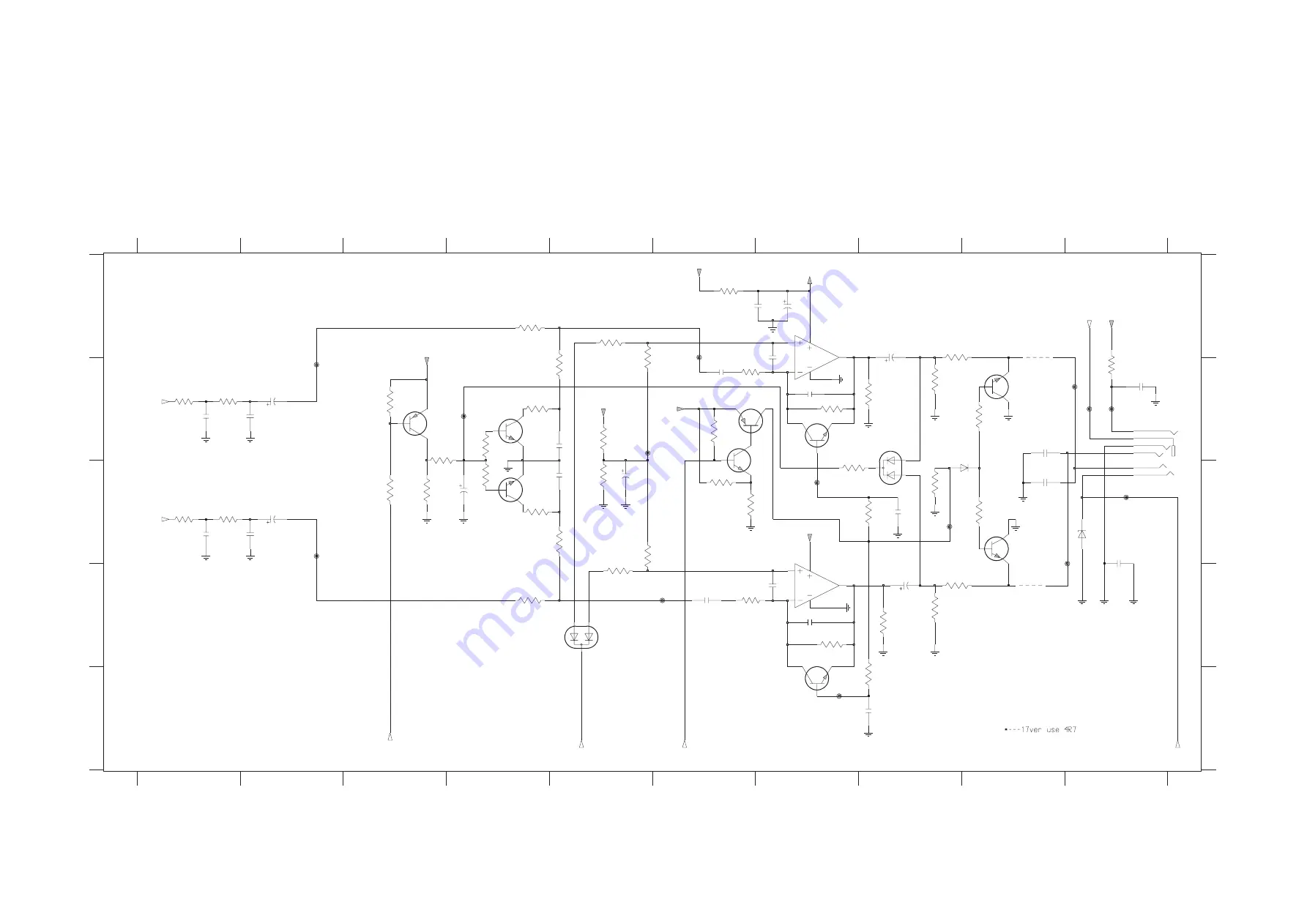
COMBI BOARD - CIRCUIT DIAGRAM
AUDIO PART

Summary of Contents for psa[cd ACT500

Page 1: ...yout diagarms Copper side view 4 4 Component side view 4 5 Exploded view diagram 5 1 Mechanical partslist 5 1 Electrical partslist 6 1 6 2 3140 785 32620 Published by LX 0334 Service Audio Printed in The Netherlands Subject to modification Portable CD Player CLASS 1 LASER PRODUCT TABLE OF CONTENTS Copyright 2003 Philips Consumer Electronics B V Eindhoven The Netherlands All rights reserved No part...

Page 2: ...ies AY3363 AAA x 2 at ESP on in at ESP on in 10 h 12h 8 h 10h 3 5 h 4h 5 h 6h lim typ E D O M Y L P P U S e g n a r e g a t l o V t e k c o s N I C D V 0 6 5 2 s e i r e t t a b y r a m i r P s e i r e t t a b Rechargable V 6 3 8 1 V 6 3 8 1 Feature Overview Low pass filter DUT S N and distortion meter L R i e Sennheiser UPM550 with FF filter Level meter i e Sound Technology ST1700B i e 4822 395 3...

Page 3: ...p on off when it is pressed for more than 2 seconds 3 esp toggle to select between the battery powersave mode and electronic skip protection esp esp ensures continuous cd playback regardless of vibrations and shocks 4 p 3 5 mm headphone socket socket to connect the player to another audio input of an additional appliance remote control socket 5 adjusts the volume 6 5 skips and searches cd tracks b...

Page 4: ...pack AY3293 wear your cd player during sport activity by securing it to the supplied hand strap waist pack 1 open the strap enclosure on the back of the hand strap waist pack and slide the cd player inside make sure the headphone remote socket is aligned to the socket hole 2 thread the strap 3 position your hand and adjust the strap until the fit is snug and comfortable batteries supplied or optio...

Page 5: ...me use the controls on the connected audio equipment and on the cd player take care when using headphones hearing safety listen at a moderate volume using headphones at high volume can impair your hearing traffic safety do not use headphones while driving or cycling as you may cause an accident general information cd play cd player and cd handling do not touch the lens A of the cd player do not ex...

Page 6: ...or off y dbb is shown if the bass enhancement is activated features selecting a track and searching selecting a track during playback briefly press 5 or 6 once or several times to skip to the current previous or next track y playback continues with the selected track and the track s number is displayed selecting a track when playback is stopped 1 briefly press 5 or 6 once or several times to selec...

Page 7: ... lifetime for longer playback press esp on the set only to enter power save mode ypowersave is displayed press esp again to return to esp mode ypowersave disappears esp on power save esp on troubleshooting troubleshooting warning under no circumstances should you try to repair the set yourself as this will invalidate the guarantee if a fault occurs first check the points listed before taking the u...

Page 8: ... which are identical with those specified be used Safety components are marked by the symbol i Le norme di sicurezza estigono che l apparecchio venga rimesso nelle condizioni originali e che siano utilizzati i pezzi di ricambiago identici a quelli specificati Componenty di sicurezza sono marcati con ñ Veiligheidsbepalingen vereisen dat het apparaat in zijn oorspronkeliijke toestand wordt teruggebr...

Page 9: ...REPAIR POSITION COMPONENTSIDE To get access to the compomentside of the printed board assembly proceed as follows 1 Remove bottom screws 2pcs under the plate decoration Remove screws 4pcs in the CD door 2 Lift the bottom cabinet 3 Remove screws 2pcs on the PCB board 4 Take care that the door switch is closed during measurements DISMANTLING THE CD DOOR To dismantle the CD door proceed as follows 1 ...

Page 10: ...466 10953 small 600x650x1 25mm 4822 466 10958 Anti static wristband 4822 395 10223 Connection box 3press stud connections 1MΩ 4822 320 11307 Extendible cable 2m 2MΩ to connect wristband to connection box 4822 320 11305 Connecting cable 3m 2MΩ to connect table mat to connection box 4822 320 11306 Earth cable 1MΩ to connect any product to mat or to connection box 4822 320 11308 KIT ESD3 combining al...

Page 11: ...vice Thereafter setting the input to high releases the reset The hardware waits for the system clock to stabilize then processes the reset interrupt Also if 0 is written to P27 and the reset is initiated by software a low level will be output The output has an N ch open drain configuration If a capacitor is to be inserted between NRST and VSS it is recommended that a discharge diode be placed betw...

Page 12: ...is selected P50 to P54 can be used for LED direct drive and P53 and P54 can be used for segment drive P60 P61 P62 P63 P64 P65 P66 P67 55 56 57 58 59 60 61 62 I O A0 SEG25 A1 SEG24 A2 SEG23 A3 SEG22 A4 SEG21 A5 SEG20 A6 SEG19 A7 SEG18 I O port 6 8 bit CMOS tri state I O port Each bit can be set individually as either an input or output by the P6DIR register A pull up resistor for each bit can be se...

Page 13: ...ission data input pins for serial interfaces 0 to 1 The output configuration either CMOS push pull or n channel open drain can be selected Pull up resistors can be selected by the P0PLU register Select output mode by the P0DIR register and serial data output mode by seri al mode regi ster SC 0MD 3 and SC1MD1 These can be used as normal I O pins when the serial interface is not used SBI0 SBI1 26 29...

Page 14: ...s for 8 bit timers 2 to 3 To use these pins as event clock inputs configure them as inputs by the P1DIR register When the pins are used as inputs pull up resistors can be specified bythe P1PLU register For timer output PWM signal output select the special function pin by the port 1 output mode register P1OMD and set to the output mode by the P1DIR register When not used for timer I O these can be ...

Page 15: ...r supply for A D converter Reference power supply pins for the A D converter Normally the values of VREF VDD and VREF VSS are used AN0 AN1 AN2 AN3 AN4 AN5 AN6 AN7 16 17 18 19 20 21 22 23 Input PA0 PA1 PA2 PA3 PA4 PA5 PA6 PA7 Analog input pins Analog input pins for an 8 channel 10 bit A D converter When not used for analog input these pins can be used as normal input pins IRQ0 IRQ1 IRQ2 IRQ3 38 39 ...

Page 16: ... pins on the LCD panel LED0 LED1 LED2 LED3 LED4 50 51 52 53 54 Output P50 NWE P51 NRE P52 NCS P53 A16 SEG27 P54 A17 SEG26 LED large current output LED driving pins SEG27 SEG26 SEG25 SEG24 SEG23 SEG22 SEG21 SEG20 SEG19 SEG18 SEG17 SEG16 SEG15 SEG14 SEG13 SEG12 SEG11 SEG10 SEG9 SEG8 SEG7 SEG6 SEG5 SEG4 SEG3 SEG2 53 54 55 56 57 58 59 60 61 62 63 64 65 66 67 68 69 70 71 72 73 74 75 76 77 78 Output P53...

Page 17: ...P61 SEG24 P62 SEG23 P63 SEG22 P64 SEG21 P65 SEG20 P66 SEG19 P67 SEG18 P70 SDO0 SEG17 P71 SDO1 SEG16 P72 SDO2 SEG15 P73 SDO3 SEG14 P74 SDO4 SEG13 P75 SDO5 SEG12 P76 SDO6 SEG11 P77 SDO7 SEG10 P53 SEG27 LED3 P54 SEG26 LED4 P80 SEG2 P81 SEG3 P82 SEG4 P83 SEG5 P84 SEG6 P85 SEG7 P86 SEG8 P87 SEG9 Write enable pin Active low Read enable pin LED0 Active low Chip select pin Active low Data acknowledge pin ...

Page 18: ...3 8 BLOCK DIAGARAM OF IC CD ESP DECODER MN662786SB ...

Page 19: ... sends play params to CD10 jump ok µP initializes radial servo loop 330ms µP releases muting via MUTE µP sends command to CD10 jump 10 tracks inside Y Y subcode ok N N Y Y N PLAY MODE N N display shows no d1SC start up stopped display shows nF d1SC start up stopped disc at nom speed within 10s N focus stability test ok µP sends new focus parameters to CD10 switch to higher focus sensitivity switch...

Page 20: ...US TEST Purpose Check movement of lens and operation of focus servo for CDDA and CDRW discs The focus servo loop is switched on and the set starts searching the focus focus ramping As soon as the focus has been found the focus servo loop is closed and the state of the focus is monitored continuously If the focus is OK the display shows F x else F x x indicates the sensitivity mode Details can be f...

Page 21: ...nd focus OK and speed OK NEXT depressed REVIEW MODE Track servo jumps 16 tracks backw Slide moves outside Slide moves inside NEXT depressed PREV depressed MODE depressed ESP depressed N Y N Y N Y N Y N Y N Y N Y N Y N Y N Y Toggle focus sensitivity see table4 BASS pressed N Y Disc motor turns clockwise accelerate Disc motor turns counter clockwise brake Slide moves outside Slide moves inside NEXT ...

Page 22: ...3 12 3 12 3 0V 3 0V 3 0V_DSP 2 8V_CD 1 5V_DSP 3 0V_DSP 1 5V_DSP 2 8V_CD 2 7V_AU 2 7V_AU 2 7V_AU 3 0V BLOCKDIAGRAM ...

Page 23: ...7406 BC857B 16V BZX384 C6V8 6304 2351 100u 470K 3339 DC JACK ESD 1301 100K 4V 220u 2345 3402 SS14 6302 3410 10M 3445 220R F211 F216 F218 F219 D GND F217 7311 BC869 F209 F114 F108 F112 F110 1M 3444 F210 D GND 100R 3354 2408 100n U9 F111 F103 F107 100K 3416 3448 D GND F105 F101 F205 F102 F201 F204 F202 100n 2331 3330 100K 3411 1K0 7304 BC869 3 2 1 100K 3420 ESD BAS316 6401 3435 10R 470R 3356 F100 2R...

Page 24: ... H C 00 22p 2121 1K0 3209 2124 100n 3118 1K0 2207 100n F315 F313 3116 F312 F310 F311 2215 100u 4V F324 3117 H 100K 3119 2114 100p 3206 1K0 100n 2204 F321 F405 F408 F409 3202 470K 3204 1K0 2117 10n SLPSW 26 TBAL 20 TEN 21 TEOUT 3 VCC 19 VREF 7 LDRCTL 16 NRFDET 15 OFTR 1 PD 6 RFIN 4 RFN 5 RFOUT 18 27 E 28 F 25 FBAL FEN 22 23 FEOUT 24 GCTL 17 GND 2 LD B 13 BDO 31 C 8 CAGC 12 CBDO 10 CEA 14 COFTR 29 D...

Page 25: ... 330p BC817 40 A A 7512 2u2 2533 4K7 3500 100K 3521 A F502 7503 BC857B BC847B 7511 7513 BC817 40 15R 3503 BC817 40 7501 6 3V 220u 2538 3511 A A 680R 7515 BC847B 12K 3501 2515 2n2 3502 2M2 330p 2531 A 2511 4u7 35V 3559 10R F510 2530 1u0 F504 F505 F513 F511 F503 F515 F506 F508 F501 F514 BAV70 6500 4V 220u 2532 680R 3544 100n 2523 2520 100n 2502 2u2 2516 1n5 18K 3526 4V 2536 47u 3515 180K 2503 33p 35...

Page 26: ...4 4 4 4 COMBI BOARD LAYOUT DIAGRAM COPPER SIDE VIEW ...

Page 27: ...4 5 4 5 COMBI BOARD LAYOUT DIAGRAM COMPONENT SIDE VIEW ...

Page 28: ...OOR OPEN 2 ACT500 409 3140 111 22891 SHAFT CD DOOR ACT500 411 3140 111 22941 SPRING CHARGING ACT500 412 3140 111 22871 SPRING BATTERY MINUS ACT500 413 3140 111 22861 SPRING BATTERY PLUS ACT500 414 3140 111 22881 SPRING BATTERY PLUS MINUS 416 3140 111 01571 SPRING DOOR OPEN ACT500 417 3140 117 69181 DOOR BATTERY PRT ACT500 418 3140 114 60441 SLIDER HOLD ACT500 419 3140 111 01581 SPRING SLIDER LOCK ...

Page 29: ...0V 2209 5322 126 11583 10nF 10 X7R 50V 2522 4822 126 13883 220pF 5 50V 2210 3198 017 44740 470nF Y5V 10V 2523 2238 586 59812 100nF 80 20 Y5V 50V 2211 2238 916 15641 22nF 10 25V 2524 4822 126 13883 220pF 5 50V 2212 2238 586 59812 100nF 80 20 Y5V 50V 2525 4822 124 23002 10µF 16V ELECTRICAL PARTSLIST COMBI BOARD CAPACITORS RESISTORS 2526 3198 017 41050 1µF Y5V 10V 3215 4822 051 30151 150R 5 0 062W 25...

Page 30: ...200 4822 242 81865 CST16 93MXW0C3 TF01 3448 4822 051 30008 0R JUMPER 5300 4822 158 10525 LAL 04T 331K 3500 4822 051 30472 4 7K 5 0 062W 5301 4822 157 50964 100MUH 3501 4822 051 30123 12K 5 0 062W 5303 4822 158 10525 LAL 04T 331K 3502 3198 021 32250 2 2M 5 3503 4822 117 12971 15R 5 0 62W 3505 4822 051 30472 4 7K 5 0 062W 3506 4822 051 30683 68K 5 0 062W 3507 4822 051 30331 330R 5 0 062W 3508 4822 0...

Reviews: