Chapter 7
7-16
V60 Ventilator Service Manual
1049766 Rev A
Component Removal/Installation
7.15 Power
Management (PM)
PCBA
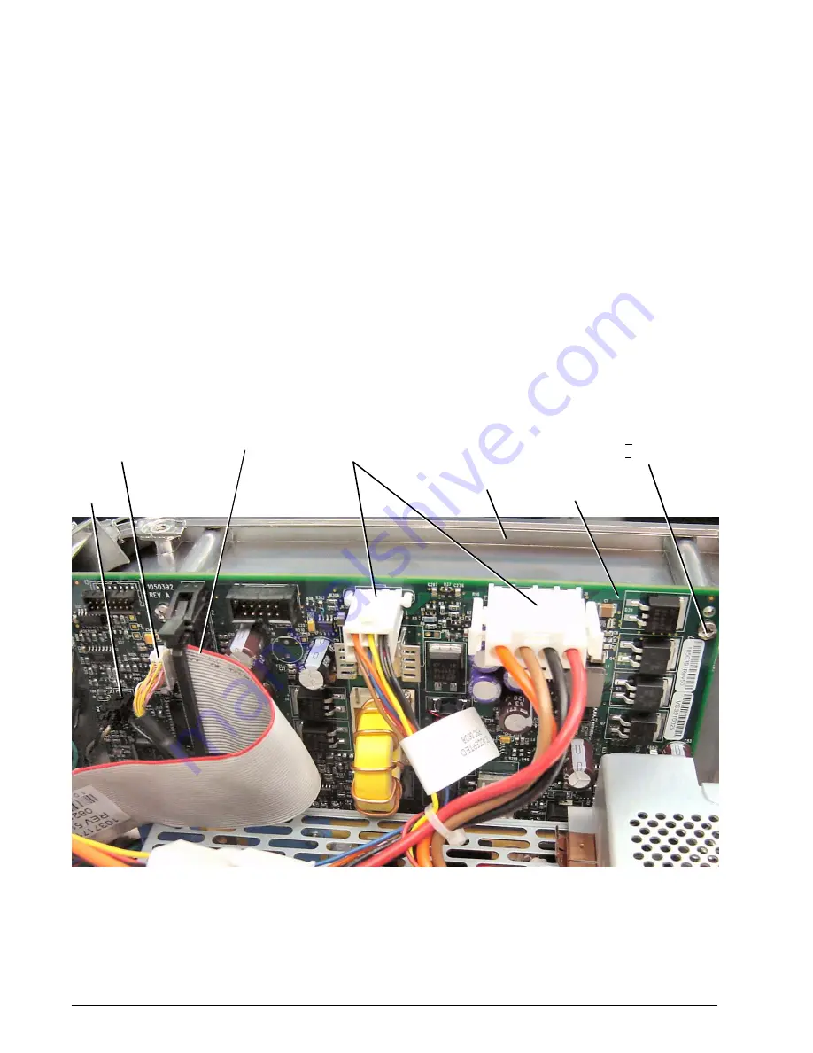
Follow these steps to remove the PM PCBA (Figure 7-15). Reverse to install.
1. Remove top cover (section 7.4).
2. Disconnect cables:
•
Speaker #2 cable
•
Power harness assembly
•
UI cable
•
LCD cable
3. Remove the screws that attach the PM PCBA to the left side wall.
4. Gently pull PM PCBA up from its connection on the CPU PCBA.
Figure 7-15: Removing the PM PCBA
M3 x 6 screw (x2)
(62 + 5.7 N cm/
5.5 + 0.5 in.-lbf)
UI
cable
Power harness
assembly
LCD
cable
Left
side
wall
PM PCBA
Speaker
cable


