background image

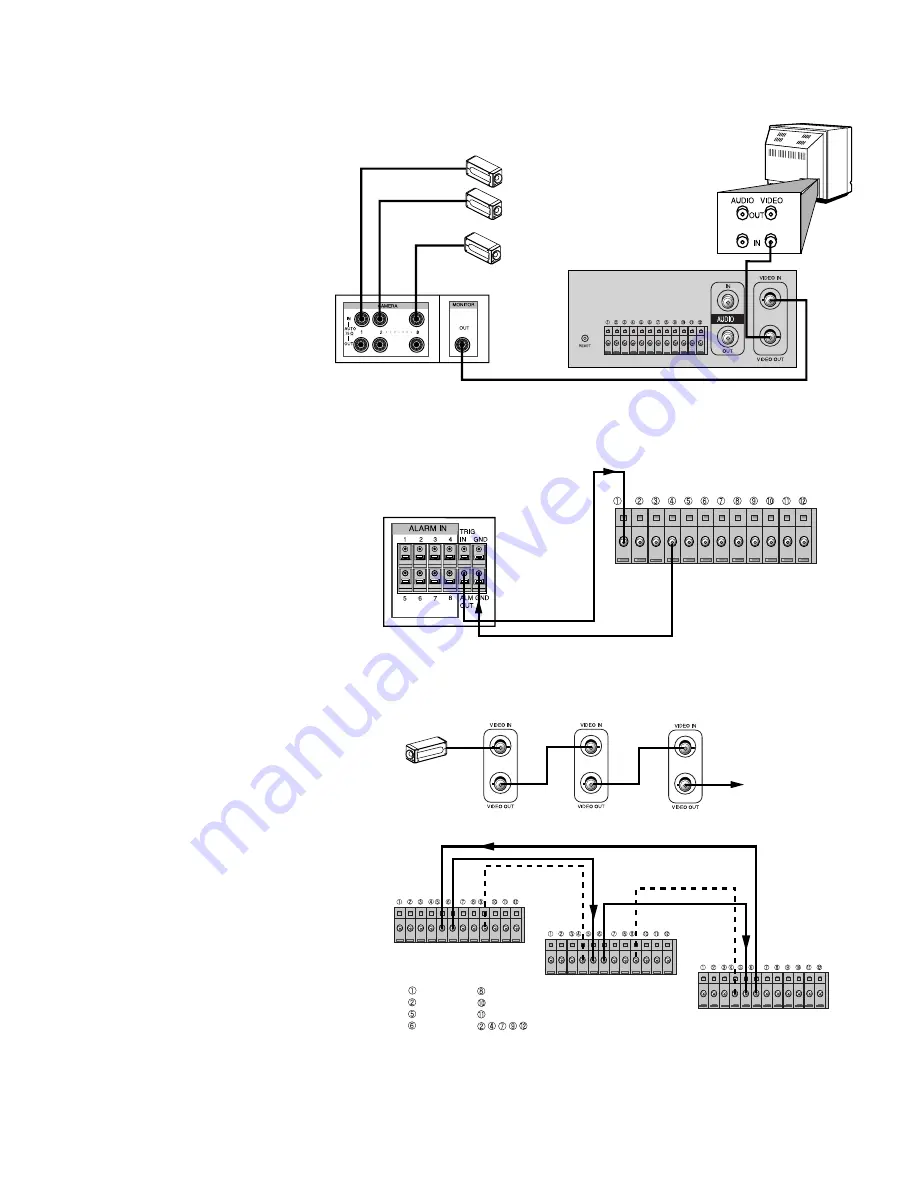
How to connect multiple cameras via
switcher:
Connect the VCR VIDEO output to the
MONITOR VIDEO input. 

Connect the SWITCHER VIDEO
output to the VCR VIDEO input.

How to connect Alarms:
Connect the SWITCHER/
MULTIPLEXER alarm output to the
VCR alarm input, and then connect the
SWITCHER/MULTIPLEXER GND to
the VCR GND pin 4.

How to connect Series Record:
Connect the first VCR to CAMERA/
SWITCHER.  Connect the other VCRs
in series.

After connecting, turn on the VCR, and
then select the ON: SERIES mode in
REC MODE menu.

1-9

CAMERA 1

CAMERA 2

.
.

CAMERA 8

MONITOR

VCR

SWITCHER

FIG. 7  - VCR  CONNECTION TO  SWITCHER

SWITCHER/MULTIPLEXER
BACK PANEL

To ALARM OUT

To GROUND

To ALARM IN

VCR BACK PANEL

To GROUND

FIG. 8 - VCR ALARM CONNECTION

CAMERA

To MONITOR's

VIDEO IN

GROUND

GROUND

VCR 1

VCR 2

VCR 3

ALARM IN
ALARM OUT
SERIES IN
SERIES OUT

VEXT
TAPE END OUT
1-SHOT REC IN
         GROUND

FIG. 9 - VCR SERIES RECORD CONNECTION

Summary of Contents for RT30A

Page 1: ...PHILIPS RT30A RT960A High Density Video Cassette Recorder Philips Communication Security Imaging Instructions for Use en fr de es nl it pt ...

Page 2: ......

Page 3: ...18 Do not place the recorder in the immediate vicinity of a heating source 19 Do not install this equipment in a confined space such as a bookcase or similar unit CLEANING 20 You can clean the recorder with a moist fluff free cloth or shammy leather cloth DISPOSAL 21 This recorder contains a battery Do not dispose of the battery with other solid waste The battery is located inside the recorder To ...

Page 4: ...Fig 4 Item 4 1 7 5 4 VCR Setup 1 8 5 5 Video Cassette Tapes 1 10 5 6 Normal Playback 1 10 5 7 Normal Recording 1 12 6 Setting the On Screen Display 1 13 6 1 CLOCK SET UP Menu 1 14 6 2 RECORD MODE SET UP Menu 1 14 6 3 TIMER RECORD SET UP Menu 1 16 6 4 REVIEW MODE Menu 1 16 6 5 SYSTEM SET UP Menu 1 17 6 6 SEARCH SET UP Menu 1 18 7 SELF DIAGNOSIS 1 19 8 TROUBLESHOOTING 1 20 9 MAINTENANCE GUIDE TABLE ...

Page 5: ...power loss for up to 2 weeks joggle shuttle for instant picture retrieval tape remaining indication and automatic recording after power failure The list is endless ensuring that these VCRs can meet your required application specification Technically the RT30A and RT960A are the most advanced Real Time video recorders available V Sync selection video through security lock video loss Vext pulse and ...

Page 6: ...packing materials and box in case you ever need to ship or store your unit 4 1 Controls and Functions Operational Controls 1 POWER button Press for on press again for off The display window becomes brighter when the VCR is switched on When you select power off the timer program is operational if the option has been setup 2 REC RECORD button Press to begin recording 3 Cassette loading slot Cassette...

Page 7: ... the Screen is reduced 16 KEY LOCK button The KEY LOCK setting allows the user to prevent changes to the setting The VCR stays in the current mode Press again to unlock 17 MENU button Press to display and change the settings of the VCR while viewing on the video monitor Display Window 1 VCR Speed indicator Displays the selected VCR speed A6 A18 A30 72 96 etc A Audio 2 ALARM indicator ALARM appears...

Page 8: ...ries OUT Pin 8 VEXT Pin 10 Tape end OUT Pin 11 1 Shot record IN Pins 2 4 7 9 12 GND 5 RESET Press to reset the VCR 1 6 AUDIO FIG 3 RT30A RT960A REAR TERMINAL FUNCTION SIGNAL LEVEL IN OUT 1 ALARM IN VIH 4 5V VIL 0 6V T above 500 msec INPUT 3 ALARM OUT VOH 4 5V VOL 0 6V T Alarm rec state OUTPUT 5 SERIES IN VIH 4 5V VIL 0 6V T above 500 msec INPUT 6 SERIES OUT VOH 4 5V VOL 0 6V T above 500 msec OUTPU...

Page 9: ...ck Audio In Accepts an audio signal from a camera external sound equipment or another recorder Line 6 dBm 47 kOhm Audio Out Provides an audio output for a monitor or another recorder 9 dBm 1 5 kOhm unbalanced 5 3 Using the 12 pin Terminals Fig 4 Item 4 Attach the wires of the alarm switch door sensor or warning lamp to the 12 pin terminal by pushing in the cable wire ALARM IN You can connect an al...

Page 10: ...ut to the MULTIPLEXER PLAYBACK input Connect the VCR VIDEO input to the MULTIPLEXER REC output Connect the VCR VEXT pin 8 to the MULTIPLEXER VEXT terminal Connect the MULTIPLEXER GND terminals to the VCR GND pin 9 1 8 VEXT MULTIPLEXER To TRIGGER IN From GROUND To GROUND CAMERA 1 CAMERA 2 CAMERA 8 MONITOR VCR FIG 6 VCR CONNECTION TO MULTIPLEXER WITH TRIGGER FUNCTION AUDIO MONITOR To AUDIO IN To VID...

Page 11: ...cord Connect the first VCR to CAMERA SWITCHER Connect the other VCRs in series After connecting turn on the VCR and then select the ON SERIES mode in REC MODE menu 1 9 CAMERA 1 CAMERA 2 CAMERA 8 MONITOR VCR SWITCHER FIG 7 VCR CONNECTION TO SWITCHER SWITCHER MULTIPLEXER BACK PANEL To ALARM OUT To GROUND To ALARM IN VCR BACK PANEL To GROUND FIG 8 VCR ALARM CONNECTION CAMERA To MONITOR s VIDEO IN GRO...

Page 12: ...ab is removed 5 6 Normal Playback Turn on the power of both the VCR and the MONITOR 1 Insert a prerecorded video cassette The indicator will light and the VCR will power up automatically If a tape without a record protect tab is inserted the unit will start the playback automatically 2 Press the PLAY button Press or button to choose the desired time mode 6H 18H 30H etc The selecting time is displa...

Page 13: ...video by single field when in the still mode To scan for alarm recordings refer to paragraph 6 6 5 6 2 Tape Counter Memory Feature Real time Counter during PLAYBACK or RECORDING mode Press the DISPLAY button Whenever you press the DISPLAY button the time counter or remaining time is displayed alternately in the VCR indicator panel When the COUNTER is displayed Counter changes to CLOCK when the cas...

Page 14: ...select 1SHOT REC OFF the unit will record one picture each time the external 1SHOT REC input is activated 3 Press the REC button Recording will start The REC indicator will light in VCR indicator panel 4 Press the STOP button to stop recording To PAUSE the recording during the RECORDING mode 1 Press the STILL button to pause the tape 2 When you want to continue recording press the STILL button aga...

Page 15: ...raphs 2 Press the button to select the respective menu option that you want to setup and then press the button to enter the menu 1 13 RECORD MODE SET UP REVIEW MODE LANGUAGE TIMER RECORD SET UP MAIN MENU SEARCH SET UP SYSTEM SET UP CLOCK SET UP DATE FORMAT DDMMYY DAY LIGHT OFF TIME HH MM SS DATE DD MM YY DAY DISPLAY LOWER R END MENU SET START END DAY SPD OFF A6 OFF A6 OFF A6 OFF A6 OFF A6 OFF A6 O...

Page 16: ... on the screen display LOWER R LOWER L UPPER L UPPER R OFF 7 Press the button the select the DISPLAY option and then press the button to change to the required selection 8 Press MENU button when finished 6 2 RECORD MODE SET UP Menu The RECORD MODE SET UP MENU enables you to define the VCR alarm options Alarm recording will start when an external alarm signal an alarm event is input to the VCR This...

Page 17: ...utton to select either 1 Field 2 Field 5 Field 10 Field 30 Field or 60 Field these are the number of fields recorded after one VEXT pulse Note Your update rate will be decreased with the same factor as the number of fields selected SERIES REC The Series Recording mode is convenient when you record with two or more VCRs If you have two VCRs in the Series Recording mode the second VCR will start to ...

Page 18: ...re finished programming and you want to set the VCR to record the programs you have entered MAKE SUREYOU HAVE INSERTED A TAPE INTO THE VCR THE POWER BUTTON MUST BE SWITCHED TO OFF BEFORE THE VCR WILL RECORD ANY TIMER PROGRAMS TIMER appears The VCR is now set to record the preset programs 6 4 REVIEW MODE Menu The REVIEW MODE enables you to display on the monitor screen the alarm events power failur...

Page 19: ...rammed the buzzer will operate 9 Press the button to select the BUZZER SELECT option and then press the button to enter the menu BUZZER SELECT menu will appear 10 Press the to choose the respective option and then press the button to select ON OFF Note The TAPE END buzzer selection is only activated when you have selected RE REC EVEN IF ALARM or STOP IF ALARM when there is no alarm in the REPEAT f...

Page 20: ...EARCH SET UP Menu The SEARCH SET UP function enables you to search for specified alarm events By entering the menu and entering the alarm number found in the ALARM REVIEW MODE menu the VCR will automatically search the tape for the alarm index To scan alarm recordings during the STOP mode when the tape is inserted 1 Press the MENU button and the main menu will appear 2 Press the button to select t...

Page 21: ...Error Reel Rotational Error Drum Motor Error DISPLAY NOTAPE NO SAFETYTAB VIDEO LOSS Check if aTape is inserted Check if a cassette has a safety tab Check if the video cable is correctly connected toVIDEO IN or problems with the video source CHECK POINT ACTION When a malfunction occurs in the VCR press the POWER button on the front of VCR to operate normally If an error message Err appears on the d...

Page 22: ...es Load cassette in direction indicated by arrow on cassette A cassette is already in theVCR Check if power indicator is lit on theVCR indicator panel If not make sure power cord is plugged in If the indicator flashes press the POWER button again The cassette has had the erase prevention tab removed Stick a piece of cellophane tape over the erase prevention tab hole or select a different cassette ...

Page 23: ...e When the VCR is exposed to a rapid temperature change from cold to warm some condensation will occur Under this condition connect the power cord to the AC line press the POWER button ON and allow at least two hours for the VCR to dry out 1 21 DRUMASSY MOTOR CAPSTAN BELT CAPSTAN BASEASSYA C HEAD F E ARMASSY IDLER ARMASSY F L CAPSTAN SOFTBRAKE CLUTCHAY PINCH ROLLERASSY Reference Changing Cleaning ...

Page 24: ...larm Recording From STOP Mode Approx 3 sec From RECORD Mode Less than 1 sec Video RT30A 50 RT960A 50 PAL color CCIR monochrome RT30A 60 RT960A 60 NTSC color EIA monochrome Input 1 0 Vp p 75 ohm unbalanced Output 1 0 Vp p 75 ohm unbalanced Horizontal Resolution Monochrome 320TV lines Color 270 TV lines Signal to Noise more than 43 dB 6 hour mode Audio Audio Recording possible in 6 18 30 hours mode ...

Page 25: ...6H 648H 0 14mm sec 0 62fields sec Intermittent No 960H 966H 1288H 0 07mm sec 0 31fields sec Intermittent No Recording Times NTSC models 60 Record Mode Actual hrs Tape Speed Recording Fields Drive Audio RT30A RT960A T 120 T 160 6H 6H 6H 8H 11 12mm sec 60fields sec Continuous Yes 18H 18H 18H 24H 3 71mm sec 20fields sec Continuous Yes 30H 30H 30H 40H 2 22mm sec 12fields sec Continuous Yes 72H 78H 104...

Page 26: ...1 24 ...

Reviews: