
Philips Semiconductors
Product specification
SA606
Low-voltage high performance mixer FM IF system
1997 Nov 07
3
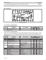
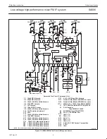
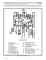
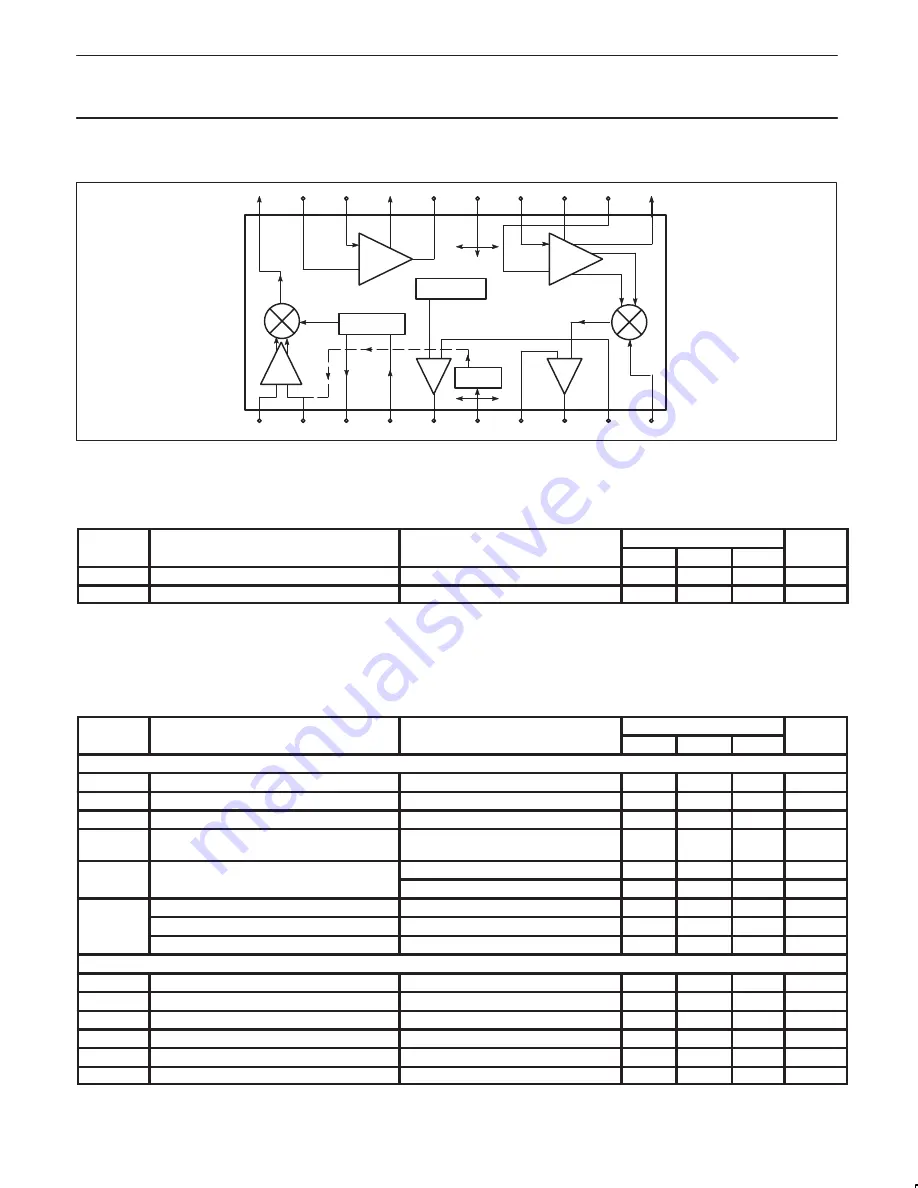
BLOCK DIAGRAM
20
19
18
17
16
15
14
13
12
11
10
9
8
7
6
5
4
3
2
1
RSSI
IF
AMP
E
B
VREG
OSCILLATOR
LIMITER
MIXER
QUAD
+ –
+
–
AUDIO
SR00348
Figure 2. Block Diagram
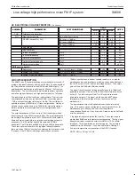
DC ELECTRICAL CHARACTERISTICS
V
CC
= +3V, T
A
= 25
°
C; unless otherwise stated.
SYMBOL
PARAMETER
TEST CONDITIONS
LIMITS
UNITS
SYMBOL
PARAMETER
TEST CONDITIONS
MIN
TYP
MAX
UNITS
V
CC
Power supply voltage range
2.7
7.0
V
I
CC
DC current drain
3.5
4.2
mA
AC ELECTRICAL CHARACTERISTICS
T
A
= 25
°
C; V
CC
= +3V, unless otherwise stated. RF frequency = 45MHz + 14.5dBV RF input step-up; IF frequency = 455kHz; R17 = 2.4k
Ω
and R18 = 3.3k
Ω
; RF level = -45dBm; FM modulation = 1kHz with
±
8kHz peak deviation. Audio output with de-emphasis filter and C-message
weighted filter. Test circuit Figure 3. The parameters listed below are tested using automatic test equipment to assure consistent electrical
characterristics. The limits do not represent the ultimate performance limits of the device. Use of an optimized RF layout will improve many of
the listed parameters.
SYMBOL
PARAMETER
TEST CONDITIONS
LIMITS
UNITS
SYMBOL
PARAMETER
TEST CONDITIONS
MIN
TYP
MAX
UNITS
Mixer/Osc section (ext LO = 220mV
RMS
)
f
IN
Input signal frequency
150
MHz
f
OSC
Crystal oscillator frequency
150
MHz
Noise figure at 45MHz
6.2
dB
Third-order input intercept point (50
Ω
source)
f1 = 45.0; f2 = 45.06MHz
Input RF level = -52dBm
-9
dBm
Conversion voltage gain
Matched 14.5dBV step-up
13.5
17
19.5
dB
50
Ω
source
+2.5
dB
RF input resistance
Single-ended input
8
k
Ω
RF input capacitance
3.0
4.0
pF
Mixer output resistance
(Pin 20)
1.25
1.5
k
Ω
IF section
IF amp gain
50
Ω
source
44
dB
Limiter gain
50
Ω
source
58
dB
Input limiting -3dB, R
17a
= 2.4k, R
17b
= 3.3k
Test at Pin 18
-109
dBm
AM rejection
80% AM 1kHz
45
dB
Audio level
Gain of two (2k
Ω
AC load)
70
120
160
mV
SINAD sensitivity
IF level -110dBm
17
dB


