1998 Feb 16
21
Philips Semiconductors
Product specification
CMOS digital decoding IC with RAM for
Compact Disc
SAA7345
PWM
MODE
, 2-
LINE
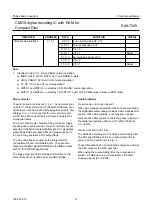
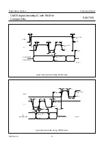
In the PWM mode the motor acceleration signal is put in pulse-width modulation form on the MOTO1 output and the
motor braking signal is pulse-width modulated on the MOTO2 output.
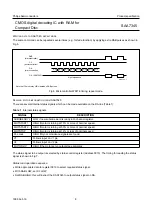
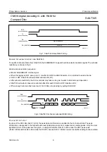
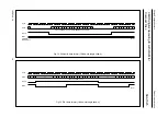
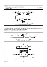
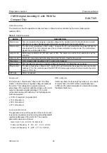
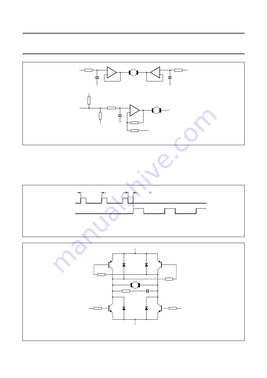
Figure 17 shows the timing and Fig.18 a typical application diagram.
MGA363 - 1
MOTO2
V
DD
VSS
MOTO1
M
22 k
Ω
10 nF
+
–
22 k
Ω
10 nF
+
–
VSS
V
SS
MOTO1
M
22 k
Ω
10 nF
+
–
22 k
Ω
22 k
Ω
VSS
VDD
VSS
22 k
Ω
22 k
Ω
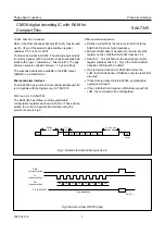
Fig.16 Motor pulse density application diagrams.
Fig.17 Motor 2-line PWM mode timing.
rep
t = 45
µ
s
t 240 ns
dead
Accelerate
Brake
MOTO1
MOTO2
MGA366
MGA365 - 2
VSS
+
M
MOTO1
MOTO2
10
Ω
100 nF
Fig.18 Motor 2-line PWM mode application diagram.

