background image

Operating and Installation Instructions

T

TIIP

P – While you are still on the ground and before mounting the rotator unit to

the support mast, temporarily connect the rotator unit to the control unit with
the control cable and perform the alignment (and basic system check) by follow-
ing Steps 2 and 5 and 8 below.

Step 1 - Rotator Unit Mounting

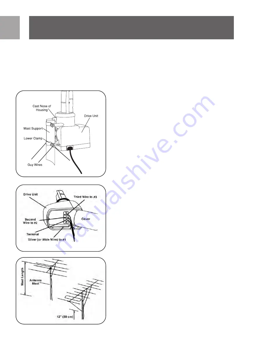
If not mounting the rotator unit inside a tower, attach the the rotator unit to

the support mast by loosening the nuts enough to slide the clamps over the
mast. Lower the rotator unit until the cast nose of the drive housing sits on top
of the support mast and tighten the nuts. Moderate tightening of the nuts with a
7/16” wrench will cause the teeth of the clamp to grip the mast securely. DO
NOT over-tighten to the point that you deform the mast, as this will reduce its
strength.
Mast Diameters of 1 1/4” to 2” (3-5cm) may be used.The 1 1/2”  (3.8 cm) size
or larger is recommended for un-guyed mast over 6’ long or where large anten-
nas are used. If guy wires are used, fasten two through each of the two holes of
the lower clamp.

Step 2 - Rotator Unit (Rotator) Connection

Up to 280’ of 20 AWG 3 conductor cable may be used. For longer runs use heav-
ier gauge wire. To attach cable to rotator unit, open the bottom cover using a
screwdriver. Remove the grommet and insert the cable through the slot. Press
the grommet back into the slot. Separate leads 1 1/4”  and strip off 1/2” insula-
tion. Find the silver (or wide jacketed lead) and connect it to terminal 1. Connect
the adjacent lead to terminal 2 and the next lead to terminal 3. If 4 wire cable is
used connect both wire 3 and 4 to terminal 3. Make sure there are no loose
strands  which can short between terminals. Recheck the wiring order and then
securely close the bottom cover. To avoid moisture collecting in the cable, be
sure the jacket passes through the grommet.

Step 3 - Antenna Mast

Antennas should be mounted as close as possible to the rotator unit. Cut 
1-1/4” – 1-1/2” mast to a length not exceeding that shown in the chart below
and mount the antenna at the top of the mast. Be sure to attach transmission
line to antenna.

• Small - Up to 5’ (1.5M) Long

5’ (1.5M)

• Medium - Up to 8’ (2.4M) Long 3’ (0.9M)
• Large - Over to 8’ (2.4M) Long

2’ (0.6M)

• Large with braces 

See Note

• Two antennas* 

4’ (1.2M)

EN

Operation and Installation

4

Fig. 1

Fig. 2

Fig. 3

Summary of Contents for SDW1850/17

Page 1: ......

Page 2: ... tr ru uc ct ti io on ns s 3 3 P Pr ro od du uc ct t D De es sc cr ri ip pt ti io on n 4 4 O Op pe er ra at ti io on n a an nd d I In ns st tr ru uc ct ti io on ns s 7 7 W Wa ar rr ra an nt ty y 7 7 T Te ec ch hn ni ic ca al l S Su up pp po or rt t ...

Page 3: ...ing between the point of entrance of the lead in and the TV and as near as prac tical to the entrance of the conductors to the building Product Description The rotator is designed to turn and accurately position even large antennas allowing best possible reception Rotation of the rotator unit is synchronized with commands from the indoor control unit to automatically go to up to 12 dif ferent memo...

Page 4: ... the lower clamp Step 2 Rotator Unit Rotator Connection Up to 280 of 20AWG 3 conductor cable may be used For longer runs use heav ier gauge wire To attach cable to rotator unit open the bottom cover using a screwdriver Remove the grommet and insert the cable through the slot Press the grommet back into the slot Separate leads 1 1 4 and strip off 1 2 insula tion Find the silver or wide jacketed lea...

Page 5: ......

Page 6: ......

Page 7: ... service please call 919 573 7863 THERE ARE NO OTHER EXPRESS OR IMPLIED WARRANTIES Philips liability is limited to repair or at its sole option replace ment of the product Incidental special and consequential damages are dis claimed where permitted by law This warranty gives you specific legal rights You may also have other rights that vary from state to state Technical Support For technical suppo...

Page 8: ...9 Instrucciones de seguridad 9 Descripción del producto 10 Instalación y operación 14 Garantía limitada por un año 14 Asistencia Técnica SP Contenido 8 ...

Page 9: ...co deberían estar ubicados fuera del edificio o dentro del edificio entre el punto de ingreso del cable de entrada y el televisor y tan cerca como sea posible de la entrada de los conductores al edificio Descripción del producto El rotor fue diseñado para girar y posicionar en forma precisa incluso antenas grandes permitiendo la mejor recepción posible La rotación de la unidad de rotor está sincro...

Page 10: ...s más largos use un cable de calibre mayor Para fijar el cable a la unidad de rotor abra la cubierta inferior usando un destornillador Remueva la arandela aislante e inserte el cable a través de la ranu ra Presione la arandela aislante nuevamente en la ranura Separe los conductores de 1 1 4 y retire 1 2 del aislante Encuentre el conductor plateado o el con ductor ancho enchaquetado y conéctelo al ...

Page 11: ......

Page 12: ...iones que se adjuntan por separado por más informa ción acerca del uso del control remoto universal Sintonice el televisor en la estación deseada en la que desea recibir Si usted no está seguro de la dirección del transmisor de la estación visite http www anten naweb org lo que podrá ayudarlo a encontrar las ubicaciones de los trasmisores locales Mientras mira la TV mueva la antena hacia delante y...

Page 13: ...d de control 2 Con la unidad apagada presione la tecla sosténgala mientras vuelve a encender la alimentación de la unidad de control Cuando las luces destellen en forma intermitente suelte la tecla 3 Apague la alimentación otra vez y vuelva a encenderla 4 Siga las instrucciones para volver a sincronizar del Paso 5 NOTA Es posible que después de tormentas fuertes deba volver a sincronizar el rotor ...

Page 14: ... original que muestre el nombre del producto y la fecha de compra Por atención al cliente o para obtener servicio de garantía sírvase llamar al 866 892 4765 NO EXISTEN OTRAS GARANTÍAS IMPLÍCITAS O EXPLÍCITAS Las obligaciones de Philips se limitan a la reparación o a su sola opción al reemplazo del producto No se aceptan reclamos por daños inciden tales especiales e indirectos de acuerdo a lo permi...

Page 15: ...SP 15 ...

Page 16: ...ons are subject to change without notice Trademarks are property of Philips Accessories and Computer Peripherals 2006 Philips Accessories and Computer Peripherals Ledgewood NJ USA Printed in China www philips com ...

Reviews: