

EN 44
12.
MCP9350i
Hardware Repair
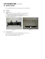
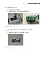
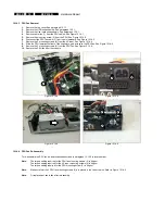
12.7. TV Tuner Card & TV Daughterboard
12.7.1. TV
Tuner
Card
Removal
1.
Remove the top cover. See paragraph 12.1.1.
2.
Remove the riser card subassembly. See paragraph 12.5.1.
3.
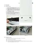
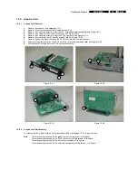
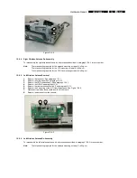
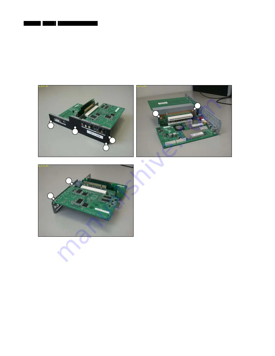
Remove the 4 mounting screws (1) from the riser card subassembly backplate. See Figure 12.7-1.
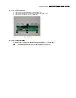
4.
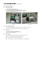
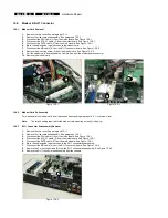
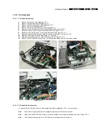
Remove the 2 mounting screws (2) from the PCI riser card. See Figure 12.7-2.
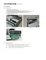
5.
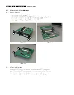
Remove the 2 mounting screws (3) from the TV tuner card. See Figure 12.7-3.
6.
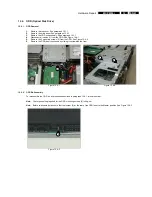
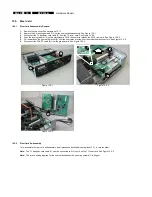
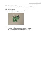
Remove together the TV tuner card and the PCI riser card from the riser bracket.
7.
Pull the TV tuner card free from the PCI riser card connector.
Figure 12.7-1
Figure 12.7-2
Figure 12.7-3
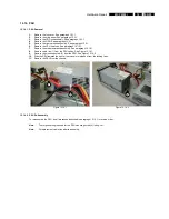
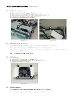
12.7.2. TV
Tuner
Card
Re-Assembly
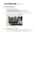
To re-assemble the TV tuner card, do all processes described in paragraph 12.7.1 in reverse order.
Note:
Make sure that the TV tuner card is inserted into the correct connector on the PCI riser card.
Note:
The torque setting required for the TV tuner card mounting screws (3) is 6kg-cm
The torque setting required for the PCI riser card mounting screws (2) is 6kg-cm
The torque setting required for the riser card backplate mounting screws (1) is 8kg-cm
1
1
1
1
2
2
3
3


