EN 50
12.
MCP9360i
Hardware Repair
12.11. FP I/O Board
12.11.1. FP I/O Board Subassembly Removal
1.
Remove the top cover. See paragraph 12.1.1.
2.
Remove the main bezel. See paragraph 12.2.1.
3.
Remove the HDD subassembly. See paragraph 12.3.1.
4.
Remove the ODD. See paragraph 12.4.1.
5.
Remove the riser card subassembly. See paragraph 12.5.1.
6.
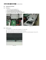
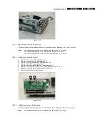
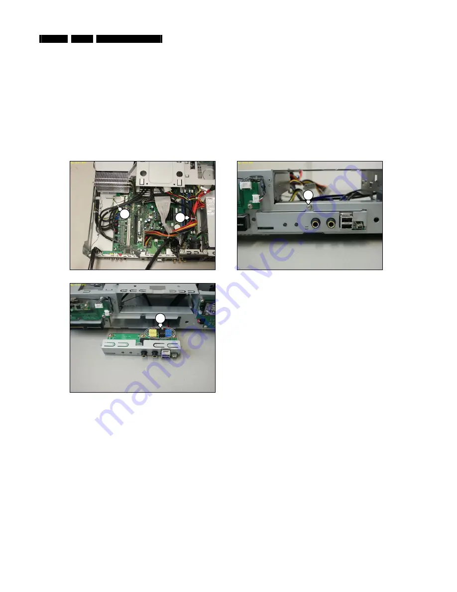
Remove the 2 cable ties (1) to allow some slack in the cables connected to the FP board. See Figure 12.11-1.
7.
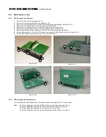
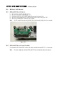
Remove the mounting screw (2) from the FP I/O board subassembly. See Figure 12.11-2.
8.
Slide the FP I/O board subassembly out from the chassis.
9.
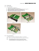
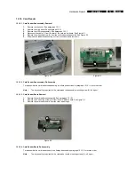
Disconnect all cables (3) from the rear of the FP I/O board. See Figure 12.11-3.
10.
Remove the FP I/O board.
Figure 12.11-1
Figure 12.11-2
2
1
1
Figure 12.11-3
3
12.11.2. FP I/O Board Subassembly Re-Assembly
To re-assemble the FP I/O board subassembly, do all steps described in paragraph 12.11.1 in reverse order.
Note:
The torque setting required for the FP I/O board subassembly mounting screw (2) is 8 kg-cm.
Note:
Fit replacement cable ties after re-assembly.


