EN 54
12.
MCP9360i
Hardware Repair
12.13.3. PSU Fan Removal
1.
Remove the top cover. See paragraph 12.1.1.
2.
Remove the HDD subassembly. See paragraph 12.3.1.
3.
Remove the riser card subassembly. See paragraph 12.5.1.
4.
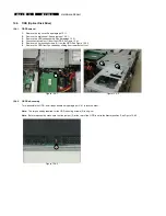
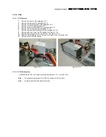
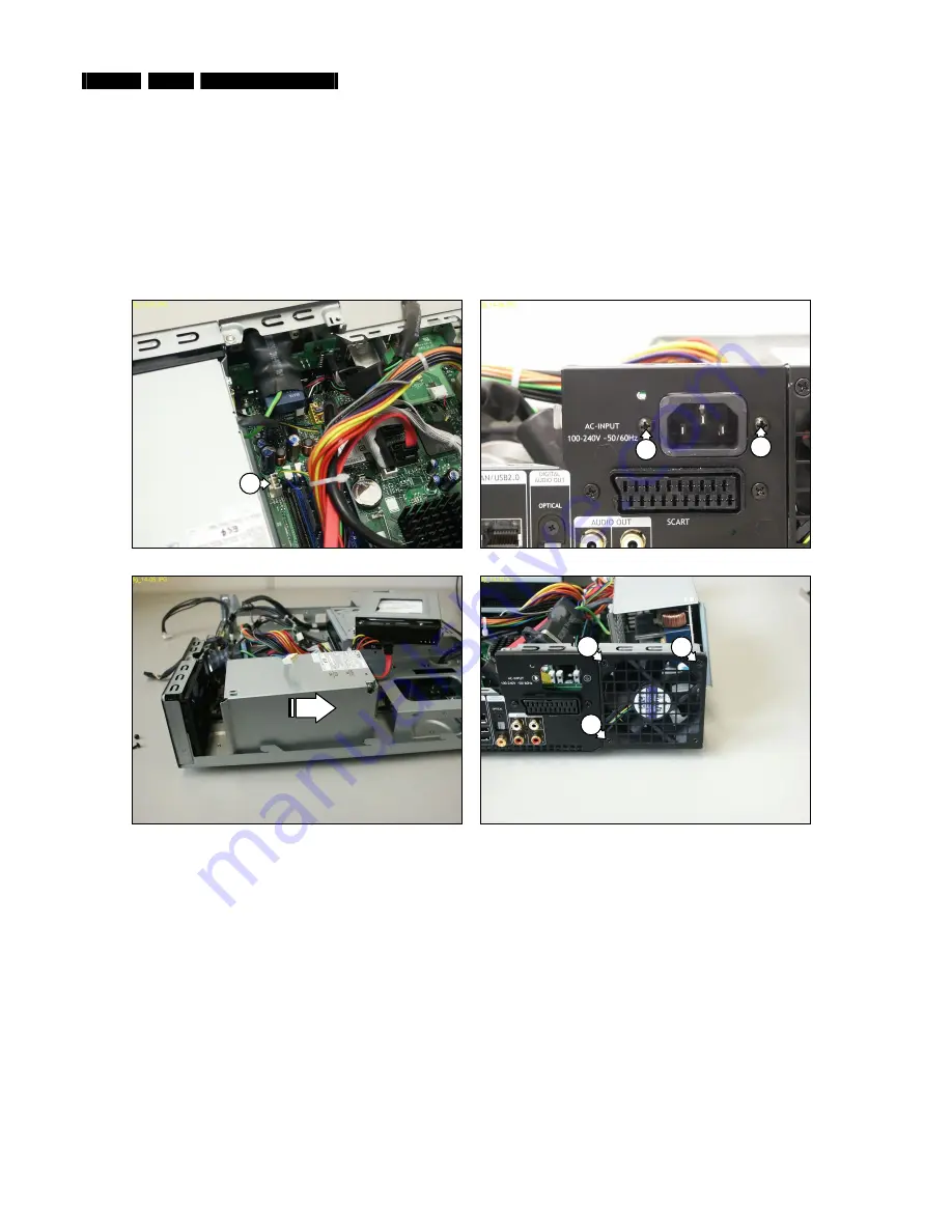
Remove cable ties (1) from the PSU cables. See Figure 12.13-1.
5.
Remove the mounting screw (2) from the PSU. See Figure 12.13-2.
6.
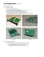
Disconnect the PSU fan cable (3) from the motherboard. See Figure 12.13-3.
7.
Remove the 2 mounting screws (4) from the AC input. See Figure 12.13-4.
8.
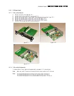
Slide the PSU towards the front of the chassis to gain access to the PSU fan. See Figure 12.13-5.
9.
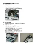
Remove the 3 mounting screws (5) from the PSU fan. See Figure 12.13-6.
10.
Remove the PSU fan from the chassis.
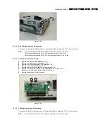
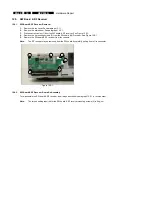
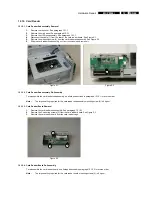
Figure 12.13-3
Figure 12.13-4
4
4
3
Figure 12.13-5
Figure 12.13-6
5
5
5
12.13.4. PSU Fan Re-Assembly
To re-assemble the PSU fan, do all steps described in paragraph 12.13.3 in reverse order.
Note:
The torque setting required for the PSU fan mounting screws (5) is 8 kg-cm.
The torque setting required for the AC input mounting screws (4) is 6 kg-cm.
The torque setting required for the PSU mounting screw (2) is 8 kg-cm.
Note:
Make sure that the 3 PSU fan mounting screws (5) are placed in the correct holes. Refer to Figure 12.13-6.
Note:
Fit replacement cable ties after re-assembly.


