background image

5 - 4

5 - 4

CD DA

T

ABASE UPGRADING PROCEDURE(waC7000)

The CD Database is provided quarterly on the in-

ternet.  

There are 2 ways to update the embedded 

CDDB. 

A) Using CD-Rom   

B) Using WADM

A. Using CD-Rom 

1. 

CDDB Update Disc Preparation 


T

ools Required :  

Y

ou will need the following items : 


- PC (Pentium III 300MHz processor or higher) 

- CD-R/R

W writer and writing application software 

- Blank CD-R or CDR

W disc 

- Broadband / High speed internet connection 

2. 

How to download the CDDB to your computer 

1.  

Register your Philips wireless audio product with 

Do

wnload the CD Database update f

iles and 

2. Unzip the .zip fi

 le and extract fi

 les into your PC.  

Note

-  

Please do not rename the fi

 lename.

-  

If you do not have the software to open the .zip 

fi 

le, please visit below website to download the 

software. 

http://www

.winzip.com/

3. Steps to update the Gracenote CDDB  

1.  

Burn the fi

 le to blank CD-R or CDR

W

. Finalize 

the disc. (The application may do this automati-

cally

.)

2. 

T

urn on the 

Audio Center

.

3.  

Insert CD into 

Audio Center

’s CD loader

, with CD 

graphic printed side facing you.

4.  

The 

Audio Center starts update the 

Audio’

embedded CDDB automatically

The message 

“Updating the 

Gracenote database” (depends on the language 

setting on the set) is shown on the display

.

Note: Do NOT power of

f the 

Audio Center or 

eject the disc at this stage.

5.  

It takes around 15-20 mins to complete CDDB 

updating.

6.  

If the CDDB is updated successfully

, the mes-

sage 

“Update Finished. Eject Disc” (depends on the 

language setting on the set) shows.

Note: If the message “Update 

Aborted. Eject Disc” 

shows, the CDDB fi

 le you downloaded maybe cor

-

rupted. Please download the zip fi

 le and burn the 

CD again.

7. 

Press eject button and then take out the disc.  

8. 

Y

ou can start the normal operation afterward. 

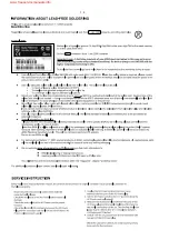
B. Using WADM 

1. How to download the CDDB to your computer 


Note: 

-  

Please do not rename the fi

 lename.

-  

If you do not have the software to open the .zip 

fi 

le, please visit below website to download the 

software.

http://www

.winzip.com/

2. Steps to update the Gracenote CDDB


Note: Do NOT power of

f the 

Audio Center at this 

stage.    

7.  

It takes around 15-20 mins to complete CDDB 

updating.

8.  

If the CDDB is updated successfully

, the message 

Update Finished

” (depends on the language 

setting on the set) shows.  

Note: If the message “

Update Aborted

” shows, 

the CDDB fi

 le you downloaded maybe corrupted. 

Please download the zip fi

 le again.  

9. 

Y

ou can start the normal operation afterward.  

www.club.philips.com

store them on your PC

1.  

Register your Philips wireless audio product with 

Do

wnload the CD Database update f

iles and 

2. Unzip the .zip fi

 le and extract fi

 les into your PC.  

www.club.philips.com

store them on your PC


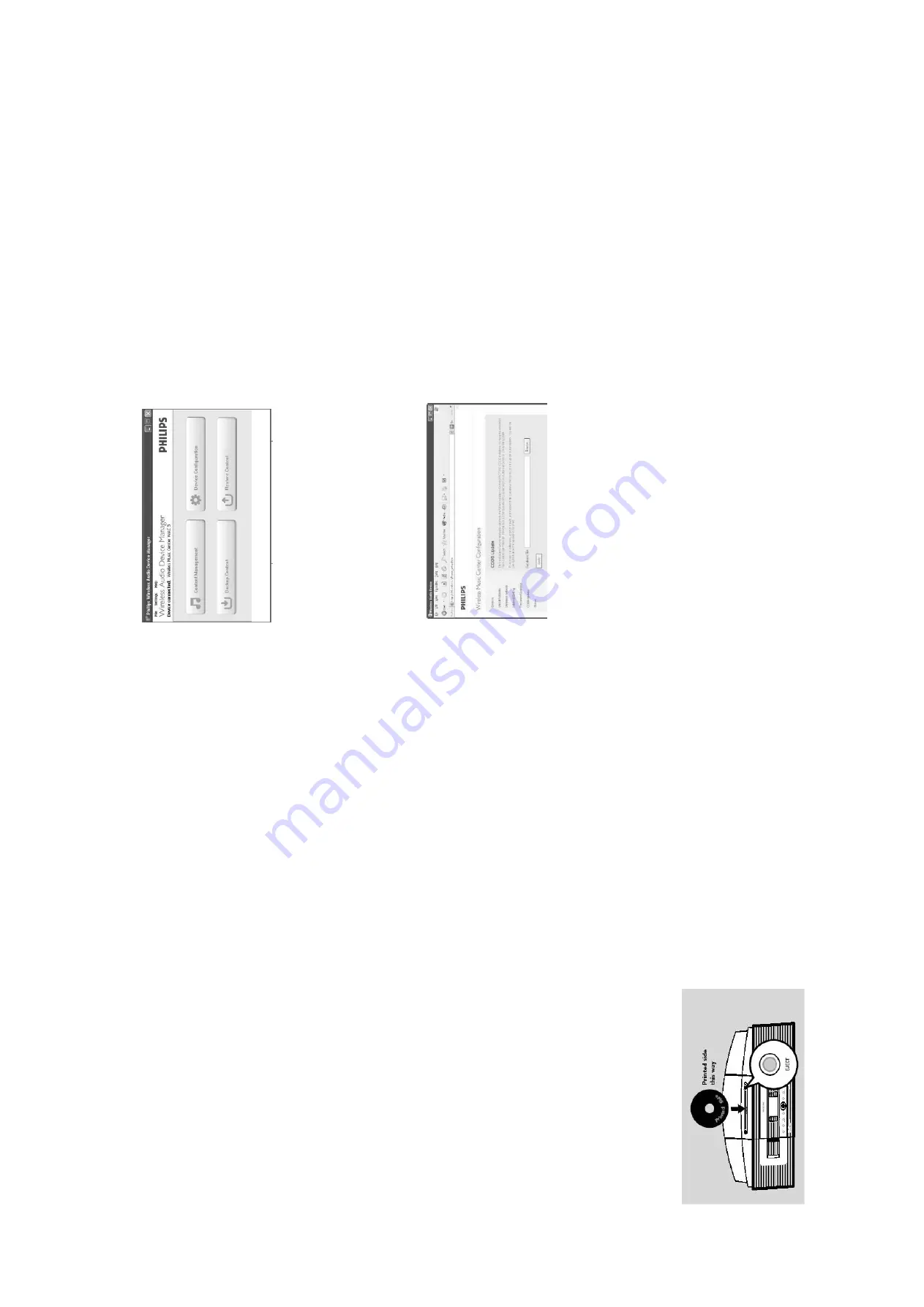
2. Launch the WADM  

3.  

4. 

➜ 

Click the

"Device configuration"

The IE browser is launched

button to start

1.  

Make sure the 

Audio Station has connected to 

the Audio 

Center

.

Click to enter the 

"CD Database update"

sub-menu

As prompted,click 

and indicate the location where you 

"Browse"

5. 

kept the firmware upgrade files on PC

Click

to start updating CD Database

6. 

Apply

www.freeservicemanuals.info

Summary of Contents for Streamium WACS7000

Page 1: ...ation Copyright 2006 Philips Consumer Electronics B V Eindhoven The Netherlands All rights reserved No part of this publication may be reproduced stored in a retrieval system or transmitted in any form or by any means electronic mechanical photocopying or otherwise without the prior permission of Philips www freeservicemanuals info ...

Page 2: ...5 AMP Socket Board waC7000 9 6 AMP Board waC7000 circuit diagram 10 1 10 2 layout diagram 10 3 10 4 Slot CD Loader Control Board waC7000 circuit diagram 11 1 layout diagram 11 2 Interface HDD to Melody Board waC7000 circuit diagram 11 1 layout diagram 11 2 Interface HDD supply Board waC7000 circuit diagram 12 1 layout diagram 12 2 Interface Ethernet waS7000 13 1 Interface IPOD waS7000 13 2 Keys RC...

Page 3: ...1 1 HANDLING CHIP COMPONENTS www freeservicemanuals info ...

Page 4: ...1 2 www freeservicemanuals info ...

Page 5: ...esponse 50Hz 12KHz 3dB S N İ72dB IEC Aux input sensitivity 500mV Headphone impedance 21 150 ȍ Wireless Wireless standard 802 11g backward compatible to 802 11b Wireless security WEP 64 or 128bit WPA AES CCM Frequency range 2142 2462 MHz channel 1 11 Transmit range 220m mp3 320kbps 150m pcm 1 6mbps Tuner FM Tuning range 87 5 108 0MHz IF frequency 10 7MHz Sensitivity limit 25dBf Image rejection 25dB...

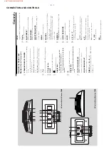
Page 6: ...to Center MUSIC BROADCAST HD broadcast music from Center to Station DBB Dynamic Bass Boost turns the bass enhancement on DBB1 DBB2 DBB3 or off VIEW toggles playback display and previous option list 8 Display shows status of the set 9 SAME ARTIST HD plays all the tracks of current Artist SAME GENRE HD plays all the tracks of current Genre SMART EQUALIZER HD selects the matched sound setting for cur...

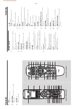
Page 7: ...d selects Radio source USB source UPnP source or the audio input from an additional connected appliance 4 1 2 3 4 navigation controls left right up down to scroll through the option list 1 HD CD returns to previous option lists Radio enters the list of preset stations Text input moves the cursor backward 3 4 HD CD skips searches tracks passage backward forward in playback screen fast scrolls the o...

Page 8: ...p timer SAME GENRE HD plays all the tracks of current Genre SAME ARTIST HD plays all the tracks of current Artist PROGRAM Radio manually programs preset radio stations Alphanumeric keys for text input MENU enters or exits setup menu SCROLL 3 4 scrolls the display screen upward or downward REFRESH sychronize remote control s display with the set s display INCR SURR selects surround sound effect DIM...

Page 9: ...3 4 CONNECTION AND CONTROLS www freeservicemanuals info ...

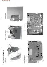
Page 10: ...cable connector c take out loudspeakers 3 Separate Front and Back Cabinet a1 remove screws T3x20 6 pcs f pull out Core Pre assembly c lift the back cabinet till the terminals sinked b remove screw M2X10 1pcs and remove ant cover d lift the back cabinet till the terminals sinked e remove screws M3X12 2pcs A A A A A A A B B B B a2 remove screws T3x10 4 pcs www freeservicemanuals info ...

Page 11: ...e screws T3x10 1 pcs and release hook 1 pcs 7 Remove Bracket CD HDD a remove screws T3x10 4 pcs b remove screws T3x6 4 pcs 8 Remove Hard Disk remove screws 314107040061 4 pcs 9 Remove HAS module remove screws T3x10 4 pcs 5 Remove cooling FAN crush rubbers 3 pcs and pull out fan b release 2 catches and pull out the shield sheet A B A A A A B B B B b remove screws T4x6 1 pcs www freeservicemanuals i...

Page 12: ...MP board and Supply module remove screws T3x12 8 pcs 11 Remove PBAS Front remove screws T3x10 12 pcs 12 Remove BTN PWR REC PRE ASSY 13 Remove COVER FNT CEN BTM and COVER FNT CEN UPPER 4 3 4 3 remove screws T3x8 2 pcs www freeservicemanuals info ...

Page 13: ... Remove STAND 2 Remove Cabinet Back Assy Screw T3x12 5 pcs Screw T3x16 5 pcs 3 Remove F CAB CENTER PRE ASSY 4 Remove Tuner Module Screw M3x6 1 pcs 5 Remove WESSLI 3A Module Screw T3x10 3 pcs A B A A A A A B B B B B www freeservicemanuals info ...

Page 14: ...5 2 4 5 DISASSEMBLY INSTRUCTION waS7000 7 Remove PBAS 6 KEYS RC from Centre Cabinet Screw T3x10 4 pcs 6 Remove PBAS 5 AF from Centre Cabinet Screw T3x8 4 pcs www freeservicemanuals info ...

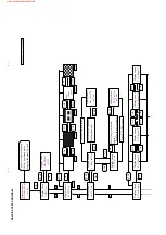
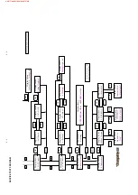
Page 15: ... OK STOP VOL VOL VOL VOL VOL VOL OK STOP Display shows 3 1Keypad Test Test all keys on pannel Disolay shows key name OK Display shows Key Test OK or Fail STOP Press STOP key twice Display shows 3 2 RC6 Test Test all keys on remote control Disolay shows key name OK Display shows RC6 Test OK or Fail Press STOP key twice STOP Display shows 4 1 Channel1 Display shows 4 2 Channel2 Display shows 4 10 Ch...

Page 16: ...splay shows WiFi MAC 012345678901 STOP Display shows Ethernet MAC 012345678901 OK STOP STOP OK Display shows Setting OK or Setting Fail Display shows 5 1Full Speed Display shows 5 2FAN Off VOL VOL OK STOP Display shows Setting Deployed OK Display shows 6 1Setting1 Display shows 6 2Setting2 VOL VOL OK STOP OK Display shows 6 3Setting3 Display shows Setting Deployed VOL VOL Display shows Resetting O...

Page 17: ...please wait and the process bar show on the display of the Audio Station The upgrade process of the Audio Station will reboot twice Note Do NOT power off the Audio Station at this stage 8 When done the Audio Station will go to the HD mode You can start the normal operations after ward 3 After the upgrade Do confi rm the software version by checking the system version Please follow the procedure des...

Page 18: ...age Update Finished Eject Disc depends on the language setting on the set shows Note If the message Update Aborted Eject Disc shows the CDDB fi le you downloaded maybe cor rupted Please download the zip fi le and burn the CD again 7 Press eject button and then take out the disc 8 You can start the normal operation afterward B Using WADM 1 How to download the CDDB to your computer Note Please do not ...

Page 19: ...6 1 6 1 SET BLOCK DIAGRAM waC7000 www freeservicemanuals info ...

Page 20: ... 14V 6 2 6 2 SET BLOCK DIAGRAM waS7000 www freeservicemanuals info ...

Page 21: ...7 1 7 1 SET WIRING DIAGRAM waC7000 www freeservicemanuals info ...

Page 22: ... 53 55 57 19 21 23 25 27 29 31 33 35 37 1500 A ROW_A 54900 001 1 6 7 8 9 10 406541 1 1602 1 2 3 4 5 1 2 3 4 5 6 GND_ESD 1300 TC38 158 01 9 8 7 1XXX 11FMN BTK A 1103 YKC21 3418 1 2 3 EARTH YKC21 3418 1400 10 2 3 4 5 6 7 8 9 1520 10FE BT VK N 1 ECO_STBY 5 FAN_ON OFF RDS IRQ 6 FM_STEREO 7 FM_TUNED MUTE 8 GND_DAC 9 HP_R 19 20 R_OUT 14 12V_A 15 L_OUT 16 GND_AI 17 R_IN 18 L_IN I2C_SDA 2 3 I2C_SCL 4 18FM...

Page 23: ...19 12 13 7 SKQNAB 1113 2 1 7124 4 74LVC00AD 1K2 3116 3115 820R F119 BC857B 7114 1K8 3118 16V 10u 2103 F102 5109 600R 10u 2108 16V 47u 2100 3 4 5 HLEM4R 1 1100 1 2 3152 F117 4K7 3166 100K 820R 3105 560R 3104 7113 BC857B F110 600R 5110 600R 5100 F115 F116 F113 F114 BC857B 2107 7104 2 GND_DAC 220u 10V SKQNAB 1109 1 F120 10K 3170 5101 600R 3100 150R 2 GND 1 OUT 3 VS TSOP4836 7121 3127 10K 2105 220n 10...

Page 24: ...8 2 8 2 KEYS RC BOARD Layout Diagram waC7000 SIDE A SIDE B www freeservicemanuals info ...

Page 25: ...349 S2B EH F314 SKQNAB 1347 F313 1 2 3 4 5 4 5 6 7 A B C D E E F G H 1225 E2 F203 C3 F204 C4 F205 C4 Standby F G H A 6 7 1 2 3 B C D 1250 C3 6207 1 F5 6207 2 F5 F201 C3 F202 C3 F201 F202 SKQNAB 1225 4 5 F205 F204 1250 HLEM4R 1 1 2 3 LTL 1BEHJ ORANGE 1 2 GREEN 3 2 6207 1 F203 6207 2 LTL 1BEHJ STANDBY KEY BOARD EJECT KEY BOARD waC7000 www freeservicemanuals info ...

Page 26: ... 3528 8K2 18K 2663 47p 3592 GND_A 2u2 2511 GND_A 10n 2544 4K7 3502 5K6 3594 470p 2666 4K7 3668 1n0 2507 2204 3663 2K2 220u 16V 3661 2K7 GND_A 5702 600R GND_A 2596 470n 2K2 3664 2u2 2503 470p 2502 2543 10n 5011 1K0 3524 8K2 GND_A 100p 2708 2665 470p 12V_A 1n0 2568 22n GND_A 2206 GND_A 100K 3712 GND_A 2n2 2517 600R 2K7 5015 A_HAS A_TU 3503 470R 3707 2589 GND_A 220n 3522 GND_A 8K2 50V 1u0 2662 8K2 35...

Page 27: ... 8 4 GND_A 7621 BC847B GND_D T053 7202 BC847B 2403 T035 100n 2222 1u0 33K GND_A 3231 470p 2227 12 13 14 4 11 T045 5V TL084 7205 4 BC817 25 7208 BC847B 7623 2235 47u 16V BC857B 7204 2905 22n 3232 3623 1K0 47K A_HP 3206 2K2 3631 T041 1K0 47R 3612 GND_A 3223 27K 8K2 3607 2628 47u 16V 12K 3407 3611 47R 2605 100p 5404 A_HP 600R 4 3640 5K6 NJM4556AM 7601 1 3 2 1 8 2212 47n 3235 1K0 3211 6K8 GND_A A_HP 1...

Page 28: ...020 5019 600R 600R 5004 1K0 3331 220R 3327 GND_D 220R 3326 470n 2962 GND_P GND_D GND_D 2973 1n0 GND_D 9V_ECO GND_D 12V_D GND_D T072 220R 3335 220R 3208 GND_D T071 1K2 3302 2972 100n 5010 600R 10n 2249 T103 T100 3299 10K 2970 2u2 50V 8K2 3303 GND_D 5007 600R GND_A 560p 2963 T097 3333 T073 6 7 8 9 220R 12 13 14 15 16 17 18 2 3 4 5 18FMN BTRK A 1401 1 10 11 T102 1102 1 2 3 4 5 05FE ST VK N T087 T111 ...

Page 29: ...9 4 9 4 PB5 AF BOARD Layout Diagram SideA waC7000 www freeservicemanuals info ...

Page 30: ...9 5 9 5 PB5 AF BOARD Layout Diagram SideB waC7000 www freeservicemanuals info ...

Page 31: ... Right Sub Left Sub Right 2995 B2 2994 B2 To HAS AMP Panel Left 1 1902 B1 1901 B3 1900 B3 C B To Left LSB C 2993 B2 B A 3 Sub Left A 1 2992 B2 2 2 3 A96 2 3 4 2995 33n 1900 B4P VH 1 WH07D 1 1902 1 2 3 4 5 6 7 33n 33n 2993 1 2 3 4 2992 B4P VH 1901 33n 2994 www freeservicemanuals info ...

Page 32: ... 3413 5K6 10K 3604 2602 100p 1311 RT 01T 1 0B 1 7 4 1 2 14 HEF4013BT 3 6 5 100n 7607 1 2418 3n3 2415 F123 2608 2600 100n 14 8 100p 7600 4 74HCU04D 9 7 11 7 14 10 22R 74HCU04D 7600 5 3610 2404 470u35V 100n 2400 7716 BC857B 100K 3606 7608 BC857B 7602 3n3 BC847B 100n 2422 7710 BC847B 2421 2403 100n 3425 5K6 5K6 3423 100n 2115 100n 2604 2603 100p 4 5 6 7 8 9 1 10 11 12 13 2 3 F142 13FE BT VK N 1602 10...

Page 33: ...9 3351 3353 3K9 3302 5R6 3305 5R6 F139 2336 330p 100n 2130 22u 2106 2107 100n 18 10 3 14 23 12 1 24 17 20 9 5 4 6 7 16 21 13 11 2 7100 Φ 15 22 19 8 AMPLIFIER POWER TDA8922TH N1 2135 68p 100n 2304 2101 100n 5R6 3105 3103 22R 3114 3K9 F112 5R6 3102 6 7 F109 1306 B7B EH A 1 2 3 4 5 100n 2117 470n 2125 2129 100n 68p 2335 2325 470n 470n 2316 3K9 3352 470n 2340 2330 100n 100n 2339 5R6 3100 3101 5R6 15n ...

Page 34: ...11 3 11 3 AMPLIFIER BOARD Layout Diagram side A waC7000 www freeservicemanuals info ...

Page 35: ...11 4 11 4 AMPLIFIER BOARD Layout Diagram side B waC7000 www freeservicemanuals info ...

Page 36: ...7BW C D E 4K7 3806 3808 1K8 3803 10K 3804 4K7 10K 3805 4 8 11 15 16 13 9 12 5 TDA7073A 7801 14 10 2 1 6 7 3 47p 2806 47p 2805 3825 10K 10K 3824 100K 3809 3821 100R 10K 3815 3810 100K 3818 10K 1K0 3816 5000 600R 3823 470R 2804 100n F011 1K0 3817 F015 F013 4005 F004 4006 F006 F005 470R 3822 2802 100n 4000 5001 600R 22K 3814 2 3 4 5 6 7 8 9 1 10 11 12 13 14 15 16 17 18 19 19FMN STK A 1802 F012 F007 3...

Page 37: ...12 2 12 2 SLOT DVD LOADER CONTROL BOARD Layout Diagram waC7000 SIDE A SIDE B www freeservicemanuals info ...

Page 38: ...23 DIOW 24 GND 25 DIOR 26 GND RDY DD2 13 DD13 14 15 DD1 16 DD14 17 DD0 18 DD15 19 GND 2 GND 1 RESET 10 DD11 11 DD3 12 DD12 10R 40FLZ RSM2 R TB LF SN 1201 3314 3310 10R 10R 3313 10R 3311 10R 3302 3327 10R 40 GND DD6 5 DD9 6 DD5 7 DD10 8 DD4 9 32 DA1 33 PDIAG 34 DA0 35 DA2 36 CS0 37 CS1 38 DASP 39 DD8 4 25 GND 26 RDY 27 CSEL 28 DMACK 29 DD7 3 GND 30 INTRQ 31 RESERVED 18 GND 19 GND 2 KEYPIN 20 DMARQ ...

Page 39: ...12 4 12 4 PB ATA MS SL Interface Layout Diagram waC7000 SIDE A SIDE B www freeservicemanuals info ...

Page 40: ...X 7 O _ W N T X C A W C _ N 1 2 3 4 1506 C4 A C C 5504 B2 5505 A2 5506 B2 2502 B2 5507 B2 5508 B2 NTC 1 2 3 5 1 2 3 4 1506 1504 S4B EH 1 2 10K S4B EH 1507 1 2 3 4 3501 12V 2 12V RETURN 3 5V RETURN 4 5V 1502 794285 1 1 390R 1206 5501 DGND DGND 5508 390R 1206 100n 2502 5507 390R 1206 390R 1206 5506 390R 1206 5504 5505 DGND 390R 1206 100n 2505 390R 1206 5502 5503 390R 1206 www freeservicemanuals info...

Page 41: ...12 4 12 4 PB ATA PW Interface Layout Diagram waC7000 SIDE A SIDE B www freeservicemanuals info ...

Page 42: ...0 RX RX GND_RJ45 RX TX 1 2 3 1 2 A B C NC NC TX GND_RJ45 TX TX RX 1601 B1 1602 B3 4 5 6 NC NC F96 3 A B C 1 2 3 4 5 6 7 8 9 10 1601 B6B PH K 1 2 3 1 406541 1 1602 Circuit diagram Layout diagram 13 1 13 1 www freeservicemanuals info ...

Page 43: ...4 1601 C1 1602 C5 5000 B2 5001 B2 5002 C2 5003 C2 UART_TXD_1 UART_RXD_1 GND_P IIC_SCL_1 IIC_SDA_1 DISABLE_RC IPOD_DETECT GND_P IIC_IRQ 3 5V_DOCK T081 5 C D T082 T083 T080 5000 600R 5004 600R 600R 5003 5002 600R 5005 600R 600R 5001 600R 5006 10n 2800 8 9 600R 5008 12 1 2 3 4 5 6 7 1602 5786767 2 10 11 11 2 3 4 5 6 7 8 9 11FMN BTK A 1601 1 10 www freeservicemanuals info ...

Page 44: ...5 120R 600R 5013 3141 3R3 1N4001 6116 6117 1N4001 7108 BC817 25 600R 5100 1106 SKQNAB BC857B 7101 3154 SKQNAB 1114 470R 3111 150R 3145 1K5 SKQNAB 1118 1N4001 6115 3168 T003 10K 1113 SKQNAB 2K2 3131 2114 220p 600R 5102 2 7 14 3 74LVC00AD 7124 1 1 7124 2 74LVC00AD 4 5 7 14 6 T001 6114 1N4001 3R3 3142 BC817 25 7110 2R2 600R 5108 3136 4100 220p 2104 4K7 3162 BAS316 6105 5101 600R 10K 3123 2K2 3144 313...

Page 45: ...PB6 KEYS RC Layout Diagram waS7000 14 2 14 2 SIDE A www freeservicemanuals info ...

Page 46: ...PB6 KEYS RC Layout Diagram waS7000 14 3 14 3 SIDE B www freeservicemanuals info ...

Page 47: ... 3523 GND_A GND_ESD 8K2 2504 50V 2u2 2503 2u2 50V 15K 3506 15K 3505 2K7 3504 470p 2501 3508 470R 2534 100p 2515 220p 2533 100p 2516 2506 1n0 220p GND_A 3502 4K7 2547 3n3 7201 T004 BC337 25 T003 GND_A GND_A GND_A 2K7 3503 1n0 2523 2641 100n 1n0 10n 2522 2544 2502 470p GND_A GND_A BZX384 C9V1 6202 GND_ESD 6203 BAS316 BAS316 6207 5K6 PGND 3546 3545 5K6 GND_A GND_A GND_A GND_A 470R 3526 GND_A 100n 264...

Page 48: ...5 5404 600R 33K 3231 T031 3225 27K 27K 3224 T045 100p 2228 7603 BC817 25 2924 47R 1n0 GND_D GND_D 3612 7622 BC857B GND_A 47p 2609 GND_A BC817 25 7604 BC847B 7621 47R 3611 3230 33K 12K 3601 100p 2605 4K7 3613 16V 47u 2235 2213 33n 5407 600R GND_D 4K7 3216 BC847B 7202 A_HP T035 BC817 25 7207 3236 4K7 GND_D 16V 22u 2612 4K7 3235 3204 2K2 2234 47u 16V 470p 2226 GND_A GND_A 5V 2401 100p 47p A_HP A_HP 2...

Page 49: ... 13 24 7210 TPA3008D2PHP AUDIO AMP 5030 80R 600R 5028 220R 3261 3208 51R 33n 2255 100p 2276 3262 220R 22K 3266 1n0 2297 T103 GND_A GND_A 47u 5019 120R 5025 2291 100p 100n 2289 GND_IN GND_IN GND_IN 2271 100n 100n 2261 2280 100u 25V 120R 5022 GND_IN T113 2279 10u 25V 100p 2288 T105 2257 220n 220n 2256 T102 47R 3257 5035 2254 33n 120R T104 100n 2296 220n 2258 25V 10u 2294 3268 220R 3251 22K GND_IN GN...

Page 50: ... A B C D E F 7 2967 B2 2968 B3 2967 330p 2975 10n 2973 100p 100R 3307 GND_D 3325 100R 220R 3324 GND_D GND_D 2958 47p GND_D 16V 220u 2240 3313 3314 3K3 1 2 3 4 GND_D 3K3 B4B EH A 1109 T082 GND_D GND_D 5029 600R T095 100p 2977 600R 5039 3309 22R 3310 22R T076 2978 100p A_TU PGND GND_D 25V 10u 2969 220R 3319 GND_A GND_A GND_D 12V_A GND_D GND_D 560p 2963 100n 2976 T085 4K7 3301 GND_D GND_D 470K 3304 2...

Page 51: ...PB5 AF BOARD Layout Diagram waS7000 15 5 15 5 SIDE A www freeservicemanuals info ...

Page 52: ...PB5 AF BOARD Layout Diagram waS7000 15 6 15 6 SIDE B www freeservicemanuals info ...

Page 53: ...t level at authorized service workshop In case of defects please replace the entire board resp the WiFi Card 3141 078 01481 HAS Printed Board Assembly Europe 2822 065 01728 WiFi Card Mini PCI 3141 078 02031 HAS Printed Board Assembly Nafta www freeservicemanuals info ...

Page 54: ... 1 1 8 3967 47K GND_DAC 4V 220u 2068 3981 22R 3132 22R 3175 22R 10V 10u 2062 3V3_PH 5001 600R 2065 10u 10V 68R 3961 3033 22R 3050 22R 22R 22R 3057 3138 22R U117 3103 R14 P13 R13 T14 U13 U16 U17 T13 R15 B7 N13 U12 T12 R12 P12 N12 U11 U14 T15 U15 P11 N11 U10 T10 R10 P10 C8 B8 A7 A8 C7 T9 U9 T11 R11 4 5 Φ 7000 8 PNX8706ET N106 3157 4 22R 47K 3010 2044 100n 3V3_PH 220R 3093 4 5 3095 4 22R 22R 3965 600...

Page 55: ...4 8 7 47 26 29 31 34 36 39 41 48 17 16 9 23 22 21 20 19 18 M29W160EB70N6 25 24 6 5 4 3 2 1 FLASH 2Mx8 1Mx16 7204 F216 3207 22R 22R 1 8 3217 1 2u2 2206 2203 100n F217 3V3_DRAM 100n 2204 FIRMWARE 0606 2 7 3225 2 22R 5012 1u5 100n 4201 2200 43 49 28 41 54 6 12 46 52 16 36 40 18 39 1 14 27 3 9 51 53 5 7 8 10 11 13 42 44 15 21 17 37 38 19 2 4 45 47 48 50 22 35 25 26 29 30 31 32 33 34 20 7203 MT48LC8M16...

Page 56: ... 8 22R F305 6302 TLMH3100 3308 22R 3323 22R 2310 100n 7301 BC847BW 1 F303 3332 20K 10K 3305 2304 100n 3327 22R 2 7 600R 5302 3310 2 22R 10K 3324 7 8 11 10 9 5311 2 TLA 6T118LF 6 100n 75R 3349 2314 3343 2K2 2316 100n 2303 330n 2302 1n0 F308 22R 3307 3347 10K 4 5 2 3 16 15 14 22R 3315 4 5311 1 TLA 6T118LF 1 5311 3 TLA 6T118LF 3 6 100n 2311 3315 3 22R 4 5 F304 22R 3319 4 F302 25M DSX530GA 1300 1 2 F3...

Page 57: ...422 D8 3423 D4 3424 D4 3425 D7 6406 D3 6407 D3 7403 A2 7404 1 D8 7404 2 E8 F401 C2 4400 A2 5410 A1 5411 A1 5412 B5 5413 B5 5414 C3 US OVS GND_FM 3423 10K 10R 3413 3 2 4 1 5 7 8 4 MM1572JN 7403 LM358P 7404 2 5 6 2454 10n GND_FM 3426 22K 4K7 GND_DAC GND_DAC 3425 600R 5428 GND_FM 22R 3418 4 6404 PGB 150V B2B PH SM4 TBT 1405 1 2 3 3412 220R GND_FM 2u2 2423 GND_FM 2427 100n GND_FM GND_FM 600R 5413 2424...

Page 58: ...14 15 16 17 18 19 2 20 21 22 1 10 11 12 13 3522 22R 1504 4 1775098 0 22p 2506 10K 3539 600R 5504 22R 3587 3 3 6 100n 2520 22R 3575 4 GND 40 S_ATA_DD 6 5 S_ATA_DD 9 6 7 S_ATA_DD 5 S_ATA_DD 10 8 S_ATA_DD 4 9 32 S_ATA_DA 1 33 NC 34 S_ATA_DA 0 35 S_ATA_DA 2 36 S_ATA_CS0_N 37 S_ATA_CS1_N 38 LED 39 S_ATA_DD 8 25 GND 26 S_ATA_IORDY 27 NC 28 29 S_ATA_DMACK_N S_ATA_DD 7 3 GND 30 S_ATA_INTRQ 31 NC 18 GND 19...

Page 59: ...7603 3 2 4 1 5 MM1572JN 3672 100R 600R 5623 2 7 3655 2 22R 5616 30R 100R 3629 600R 5628 F619 F616 3618 47K F651 5614 600R F650 47p 2641 3V3 F633 5631 600R 33R 3665 3623 10K 2n2 2636 F647 F612 D2 D2 7 D1 D1 8 D0 D0 9 RD E 25 26 21 LED 22 LED 23 LED 24 LED 3 D5 D5 4 D4 D4 5 D3 D3 6 VCC VCC 15 GND 16 GND 17 VCC A 18 VCC A 19 GND 2 D6 D6 20 VCC 1 D7 D7 10 WR R1W 11 RS RS 12 RESET RESET 13 CS CS 14 160...

Page 60: ... GND_DAC 20V 4u7 2726 7707 BC847BW F749 3737 1M0 F747 4707 GND_DAC 4 GND 1 IN1 2 IN2 3 ON_ 7 OUT1 OUT2 6 5 SET 7702 ST890C 8 FAULT_ 470R 3728 GND_A0 1M0 3740 100n 2705 1K0 5V_CD 5V_CD 5724 F737 3755 220R 10K 3704 100n 2701 3764 3K3 1 600R 5733 3743 3711 68K 47R 47K F735 F732 3724 1K0 5722 5720 1K0 GND_A0 2730 4u7 20V 4706 220p 2708 22K 3762 12V_A 3 2 1 8 4 GND_DAC 7708 1 LM358P 600R 5715 F712 5717...

Page 61: ...832 2 2 7 22R 3842 1 22R 600R 5801 3849 22R 3819 2 22R 2 7 3V3_EPM_INIT 22R 3851 1 8 3 6 22R 3827 1 3841 3 22R 22R 3802 2 3V3_EPM_INIT 22R 3833 2 2 7 3 6 22R 3818 3 3802 1 22R 3804 10K 8 F801 3813 1 22R 1 22R 3844 4 2810 220p 3801 22R 3862 1 1 8 4 5 22R 3827 4 22R 22R 3819 3 3 6 4 5 3 6 22R 3841 4 1 8 3813 3 22R 3832 1 22R 22R 3842 2 10K 4 5 3806 22R 3813 4 22R 3853 3800 22R 3862 2 22R 2 7 22R 1 8...

Page 62: ...u2 2911 F901 100n 2903 220n 2913 4902 1R0 3901 F903 6900 STPS2L30A 4903 100n 2905 F904 F911 33K 3908 1R0 3900 F905 100n 2910 3V3 4K7 3910 T INP 2 NC 4 OUTP 1 1 5A 1902 7905 CD 5 GND 3 1905 3V3 NCP303LSN28 3913 1 1K5 2916 100n 100n 2901 220p 2908 22u 5902 7 22n 2917 1 2 3 4 5 6 4 GND 5 12V_ECO 6 7 1903 B5B PH SM4 TBT LF 1 5V_CD 2 GND 3 12V_CD 1901 S5B PH SM4 TB 5900 30R 4 100n 2900 1 2 5 6 3 F910 7...

Page 63: ...SA U T A T A C D I N G A R I Z O M M O N A T A 314107801691 1 For PBAS 314107801231 MOD WessLi 06 FULL VERSION 314107801241 MOD HasLi 06 FULL VERSION 314107801981 MOD HasLi 06 WAC 7K_KOREA 314107801991 MOD HasLi 06 WAC 7K_OVS H D D C n g D O C K I N E B U G D E B U PBAS HasLi 06 WAC 7K_KOREA 314107801971 MOD HasLi 06 WAC 7K_USA G _ T R D O C K R A M 3 2 M B O N D O C K I N 314107801481 31410780193...

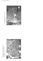
Page 64: ...16 12 16 12 LAYOUT DIAGRAM side A www freeservicemanuals info ...

Page 65: ...16 13 16 13 LAYOUT DIAGRAM side B www freeservicemanuals info ...

Page 66: ...074 03321 1007 3139 118 56981 0214 3141 074 01703 0210 3141 074 01694 0465 3141 071 20321 3141 077 51041 3141 077 51051 0287 3141 074 03311 3141 074 03441 0284 3141 077 50461 1011 3141 078 01711 3141 078 01631 1001 3141 078 01621 0102 3141 074 01171 1002 3141 070 50321 1003 2422 542 00038 2422 542 00039 0104 3141 071 20541 1005 3141 077 10191 0206 3141 077 50492 www freeservicemanuals info ...

Page 67: ...0100 0102 0104 0117 0118 0119 0108 0113 1000 1003 1001 1002 1003 1005 1007 1021 0463 17 2 17 2 EXPLODED VIEW DIAGRAM waS7000 www freeservicemanuals info ...

Page 68: ...2422 076 00717 ANT WIFI 2450MHZ 50R Y 1005 3139 118 56981 PCBAS ANTENNA MC i250 37 1006 8241 150 15021 MODULE LCM WAS 7000 1007 3141 0780 1741 PBAS 5 AF WAS7000 RDS 05 12 1007 3141 078 01751 PBAS 5 AF WAS7000 NON RDS 37 1009 3141 078 02141 PBAS 8 IPOD INT WAS7000 1020 3141 078 01771 PBAS 6 KEYS RC WAS7000 1021 3141 078 01761 PBAS 9 Ethernet WAS7000 8000 3139 111 04471 FFC FOIL 10P 180 10P BD 8001 ...

Page 69: ...9 118 56981 PCBAS ANTENNA MC i250 37 1008 8241 150 15011 MODULE LCM WAC 7000 1009 3141 078 01811 MODULE DVD Slotloader 2006 1011 3141 078 01711 PBAS 5 AF W O RDS WAC7000 05 37 1011 3141 078 01631 PBAS 5 AF RDS WAC7000 12 1012 3141 078 01641 PBAS 9 AMP SOCKET WAC7000 1014 3141 078 01651 PBAS 6 KEYS RC WAC7000 1015 3141 078 01661 PBAS 7 STBY KEY WAC7000 1016 3141 078 01671 PBAS 8 EJECT KEY WAC7000 1...

Page 70: ...REVISION LIST 18 1 Version 1 0 3141 785 31350 Draft release www freeservicemanuals info ...

Reviews: