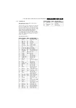
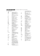
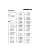
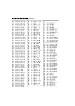
background image

Circuit Diagrams and PWB Layouts

 19

TC8.1L CA

7.

Side AV & I/O Panel

Layout Side AV & I/O Panel (Top Side)

S

IDE AV I/O PANEL

D

D

H_176

3

0_012.ep

s

201107

40-TB9

3

PH-

S

IC1XG

H_176

3

0_012.ep

s

201107

40-TB9

3

PH-

S

IC1XG

Personal Notes: 

E_06532_012.eps

131004

Summary of Contents for TC8.1L CA

Page 1: ... Television Chassis TC8 1L CA H_17630_000 eps 271107 Contents Page 1 Technical Specifications Connections and Chassis Overview 2 2 Safety Instructions Warnings and Notes 3 3 Directions for Use 4 4 Mechanical Instructions 5 5 Service Modes Error Codes and Fault Finding 7 6 Block Diagrams Test Point Overview and Waveforms Block Diagram Mono Carrier 13 7 Circuit Diagrams and PWB Layouts Mono Carrier ...

Page 2: ...ive Normal operation W 84 85 74 44 Stand by W 7 Dimensions W H D mm 594 458 486 Weight kg 21 6 1 2 Side and Rear Connections Figure 1 1 Rear and Side I O connections Note The following connector color abbreviations are used acc to DIN IEC 757 Bk Black Bu Blue Gn Green Gy Grey Rd Red Wh White and Ye Yellow 1 2 1 Rear I O Connections Cinch Video YPbPr In Gn Video Y 1 VPP 75 ohm jq Bu Video Pb 0 7 VP...

Page 3: ...he customer 2 2 Maintenance Instructions We recommend a maintenance inspection carried out by qualified service personnel The interval depends on the usage conditions When a customer uses the set under normal circumstances for example in a living room the recommended interval is three to five years When a customer uses the set in an environment with higher dust grease or moisture levels for exampl...

Page 4: ... the serial number example BF2A0635000001 indicates the number of the alternative B O M Bill Of Materials that has been used for producing the specific TV set In general it is possible that the same TV model on the market is produced with e g two different types of displays coming from two different suppliers This will then result in sets which have the same CTN Commercial Type Number e g 28PW9515...

Page 5: ...ing disconnect the mains power cord before you remove the rear cover 1 Remove all the fixation screws of the rear cover 1 and 2 2 Now pull the rear cover backwards and remove it Figure 4 1 Rear Cover removal SL5 styling 4 2 Assy Board Removal Sometimes it can be necessary to swap a complete assy or Printed Wiring Board PWB How that can be done is explained below 4 2 1 Side IO Keyboard Panel Remova...

Page 6: ...Carrier Removing cables and repositioning the panel For better accessibility of the Mono Carrier do the following see next figure 1 If necessary disconnect some cables and move the panel somewhat to the left Then flip it 90 degrees with its components towards the CRT Figure 4 7 Service position Mono Carrier 4 4 Set Re assembly To re assemble the whole set do all processes in reverse order Be sure ...

Page 7: ...ry Mode see chapter 8 Alignments 5 2 Error Codes Not applicable for this chassis 5 3 Fault Finding 5 3 1 No Picture No Sound No Raster Fuse Broken Figure 5 1 Flow chart No Picture No Sound No Raster Fuse Broken No Picture no sound no raster Fuse Broken Is D833 B Shorted to earth Is D of Q801 Shorted to to earth Is D801 D804 OK Replace D801 D804 Check B C of Q402 Check Q801 Check IC 801 NO NO NO YE...

Page 8: ...no raster B OK Check 5V supply pin 9 of IC 201 OK Check H out waveform Pin 13 of IC 201 OK Check waveform C of Q401 OK Check waveform C of Q402 OK Is IC201 Pin9 shorted to earth Yes Replace Q401or R401 Yes Replace IC 201 Yes o N o N No Replace Q402 No Check 5V 9V Circuit No Yes H_17130_012 eps 070507 No Picture Raster Sound OK Check RGB O P Pin 49 50 51 52 of IC 201 OK Check RGB drive O P Q501 Q50...

Page 9: ... No Check Q624 Q625 Q093 is OK Yes No Check Pin31wave of IC201 OK Check Vol Pin 3 Mute Pin10 of IC601 OK Yes Yes Replace IC 601 Yes NO Yes Change the damaged component No Check BTSC Module IC1001 OK No Yes Change the damage component or Replace BTSC Module No Check IF circuit or Replace IC201 No H_17630_015 eps 271107 H_17130_014 eps 070507 No colour Colour system is Right Dose the TV signal too w...

Page 10: ...izontal Line H_17130_015 eps 070507 One horizontal line Check Deflection yoke Terminal OK Replace Yoke coil Check V output Pin 5 of IC 301 OK Check V input Pin 1 of IC 301 OK Check R314 C301 R317 R336 C309 No Check R405 Fuse D402 No Yes Check 24v supply Pin 2 of IC 301 OK Yes Yes No Check V output Pin 16 of IC 201 No ...

Page 11: ...ome Waveforms Figure 5 7 FBP pin 12 of IC201 Figure 5 8 H_out pin 13 of IC201 Figure 5 9 Q402 C Figure 5 10 Q815 drain when stand by Figure 5 11 Q815 drain H_17130_016 eps 240407 H_17130_017 eps 240407 H_17130_020 eps 240407 H_17130_021 eps 240407 H_17130_022 eps 240407 ...

Page 12: ...Service Modes Error Codes and Fault Finding EN 12 TC8 1L CA 5 Personal Notes E_06532_012 eps 131004 ...

Page 13: ... D804 Q815 IC801 TEA1506 T803 Transformer 112V 22V 12V Tuner TU101 IF AMP Q101 SAW F1859 Toshiba 8891 8893 IC201 Video Amp CRT Board R G B CRT R G B V Amp IC301 V out H Drive AMP Q401 Q402 H out FBT T402 175V 24V EHT FOCUS SCREEN E2 PROM IC001 KEY IR001 Sensor Audio Amp IC601 Interface AV1 AV2 YUV AV Out Speaker MSP 3425 IC1001 AGC Optical coupling SIF H_17630_001 eps 291107 ...

Page 14: ...14 TC8 1L CA 7 Circuit Diagrams and PWB Layouts 7 Circuit Diagrams and PWB Layouts Mono Carrier H_17630_002 eps 201107 A A MONO CARRIER 40 TB59PH MAE1XG ...

Page 15: ...Circuit Diagrams and PWB Layouts 15 TC8 1L CA 7 Layout Mono Carrier Top Side 40 TB59PH MAE1XG H_17630_003 eps 201107 ...

Page 16: ...16 TC8 1L CA 7 Circuit Diagrams and PWB Layouts Layout Mono Carrier Bottom Side 40 TB59PH MAE1XG H_17630_004 eps 221107 ...

Page 17: ...Circuit Diagrams and PWB Layouts 17 TC8 1L CA 7 CRT Panel 40 TB93PH MAF1XG H_17630_005 eps 201107 CRT PANEL B B Layout CRT Panel Top Side H_17630_006 eps 201107 40 TB93PH MAF1XG ...

Page 18: ...rams and PWB Layouts BTSC Panel H_17630_005 eps 201107 BTSC PANEL BTSC BTSC 40 TB59PH MPC1XG Layout BTSC Panel Top Side Layout BTSC Panel Bottom Side H_17630_009 eps 201107 40 TB59PH MPC1XG H_17630_010 eps 201107 40 TB59PH MPC1XG ...

Page 19: ...d PWB Layouts 19 TC8 1L CA 7 Side AV I O Panel Layout Side AV I O Panel Top Side SIDE AV I O PANEL D D H_17630_012 eps 201107 40 TB93PH SIC1XG H_17630_012 eps 201107 40 TB93PH SIC1XG Personal Notes E_06532_012 eps 131004 ...

Page 20: ...20 TC8 1L CA 7 Circuit Diagrams and PWB Layouts Personal Notes E_06532_013 eps 131004 ...

Page 21: ...put the new values into the memory leave the factory mode with the MENU button on the remote control 8 2 Adjustment of the B BAT voltage 1 Apply the Philips standard test pattern to the RF input 2 Connect a DC voltmeter range 200 V to ground and jumper J809 1 3 Adjust potentiometer VR840 2 in STANDARD mode in such a way the voltage reading is 120 2 5 V Note in sets where VR840 is not present this ...

Page 22: ...amplitude of a b c and d to the same magnitude Figure 8 3 Waveform video signal 8 6 White Balance Adjustment 8 6 1 44 Region sets Normal color temperature adjustment 1 Apply the following black and white pattern in Natural status black side Y 5 1 Nits low light white side Y 80 10 Nits high light 2 Change the color temperature to Normal Status 3 Use a color analyzer to measure the black side of the...

Page 23: ... 44 sets 08 3F C2 83 09 FF FAC 08 RFAGC BRTS OSD OSDF CCD OSD CCD OSDF TXCN RGCN 25 00 21 53 4A 65 10 09 FAC 09 V01 V05 V10 V25 V50 V75 V90 V100 VOLMAX 15 1F 2F 38 6C 6E 70 71 32 FAC 10 CURTCEN VOLX PWTM MODE4 MODE5 MODE6 MODE7 MODE8 MODE9 A5 75 08 12 09 1F 15 2D 0B FAC 11 CON1 CON2 CON3 STSADJ ALI 1 ALI 2 ALI 3 06 06 02 00 0A 0A 03 FAC 12 SVM SVM1 OSD2 OSDF2 SYNC SYBBN SYBBN SYSR BBCT 10 10 28 64...

Page 24: ...oshiba TPMA8891 processor decoder and has the following key components 9 2 Chassis Block Diagram Below find the chassis block diagram Figure 9 1 Chassis block diagram Item Name of IC Function IC201 TMPA8891CXBNG MCU Decoder TU101 FSBP05P 3 E Tuner Z101 K2966M SAW Filter IC001 AT24C08A EEPROM IC601 TDA7496SA Audio output amplifier IC901 HCF4053B Analog Switch IC301 LA78040N E Vertical Deflection Ou...

Page 25: ...terfece Ext x1 Int x1 AFT OSD R G B Ys I Font 16 x 18 Display 32C x 12L Color 8 Character 384 Half tone Transparent CCD Y Proc C Trap Black stretch Y gamma Sharpness Base Band Proc TINT 1H DL Int Ext switch Color Uni color RGB Matrix ROM 㧠㧤 kB RAM 2kB ROM correction Sound TRAP IF AGC AGC DET Reg FM DEMO De emp on off ALC BPF SW VM AU Monitor out 1 H Lout SIF out AU Monitor out 2 C V3 CVBS Video SW ...

Page 26: ...ess Select 4 SCL I2C Bus Serial Clock 5 SDA I2C Bus Serial Data 6 7 BP Supply Voltage Tuner Section 5V 8 AFC Automatic Frequency Control 9 BT Supply Voltage Tuner Section 31V 10 n c IF1 11 IF2 Intermediate Frequency Out H_17130_029 eps 240407 Block Diagram Pin Configuration Top View VOLUME OP AMP MUTE STBY PROTECTIONS 1 470nF INR 30K VOLUME OP AMP 30K 1000µF 1000µF 1µF 10K 5 470nF INL 8 S_GND 2 14...

Page 27: ...A78040N E 9 3 7 Q402 BU4508DZS Q402 is a high speed switching high voltage PNP power transistor with a built in damper diode designed for use in horizontal deflection circuits The pinning is as follows Figure 9 6 Pinning of Q402 BU4508DZS Block Diagram H_17130_031 eps 240407 Pin Configuration 1 7 H_17130_033 eps 240407 b c e Rbe 1 2 3 case PIN DESCRIPTION 1 base 2 collector 3 emitter case isolated...

Page 28: ...IC Data Sheets EN 28 TC8 1L CA 9 9 3 8 IC801 TEA1506P IC801 is a switched mode power supply control IC Its block diagram and pinning are as follows Figure 9 7 Block diagram of IC801 TEA1506P Block Diagram H_17130_032 eps 240407 Pin Configuration ...

Page 29: ..._CTR_I O_1 IN OUT D_CTR_I O_1 9 D_CTR_I O_0 IN OUT D_CTR_I O_0 10 ADR_SEL IN I2C BUS address select 11 STANDBYQ IN Stand by Low active 12 I2C_CL IN OUT I2C clock 13 I2C_DA IN OUT I2C data 14 I2S_CL I2S clock 15 I2S_WS I2S word strobe 16 I2S_DA_OUT I2S data output 17 I2S_DA_IN1 I2S1 data input 18 ADR_CL ADR clock 19 DVSUP Digital power supply 5 V 20 DVSS Digital ground 21 I2S_DA_IN2 I2S2 data input...

Page 30: ...579545 MHz NTSC 4 43 4 433619 MHz this is a VCR norm it is not transmitted off air NVM Non Volatile Memory IC containing TV related data for example options O C Open Circuit OSD On Screen Display PAL Phase Alternating Line Color system used mainly in Western Europe color carrier 4 433619 MHz and South America color carrier PAL M 3 575612 MHz and PAL N 3 582056 MHz PCB Printed Circuit Board or PWB ...

Page 31: ... 50V C245 9965 000 14037 1μF 20 50V C246 9965 000 13961 47μF 20 16V C248 9965 100 07896 10nF 80 20 50V C273 9965 000 13961 47μF 20 16V C301 9965 000 15112 0 1μF 5 50V C302 9965 100 03161 220μF 20 35V C303 9965 000 14598 100μF 20 35V C304 9965 000 35325 10pF 5 50V C305 9965 000 15084 22μF 20 16V C306 9965 000 30711 1000pF 20 50V C307 9965 000 14039 4 7μF 20 50V C308 9965 000 22932 1000pμF 20 25V C3...

Page 32: ...2W R811 9965 100 03107 1 2kΩ 5 1 6W R812 9965 000 31774 3 3kΩ 5 0 16W R813 9965 100 03187 100Ω 5 1 4W R814 9965 000 14048 10Ω 5 1 6W R815 9965 100 03191 0 08Ω 5 2W R816 9965 000 24348 22kΩ 5 1 4W R817 9965 000 15664 2 2kΩ 5 1 4W R818 9965 000 14055 33kΩ 5 1 6W R819 9965 100 03184 330kΩ 5 1 6W R820 9965 000 14059 22Ω 5 0 25W R821 9965 000 13960 470Ω 5 0 16W R822 9965 100 03185 390kΩ 1 6W R829 9965 ...

Page 33: ...1015Y PNP Q802 9965 100 03003 2SC1815 Y Q815 9965 100 03176 2SK2645 01MR Q841 9965 100 03003 2SC1815 Y Q842 9965 100 03003 2SC1815 Y Q843 9965 100 03175 2SD2012 Q844 9965 100 03003 2SC1815 Y Q845 9965 100 03003 2SC1815 Y Q903 9965 100 03003 2SC1815 Y Q905 9965 100 03003 2SC1815 Y J012 9965 100 01107 Audio Cable 1500mm J018 9965 100 01107 Audio Cable 1500mm J019 9965 100 01107 Audio Cable 1500mm J1...

Page 34: ...Revision List EN 34 TC8 1L CA 11 11 Revision List Manual xxxx xxx xxxx 0 First release ...

Reviews: