Mechanical Instructions
4.
4.
Mechanical Instructions
Index of this chapter:
4.1 Set Disassembly
4.2 Assy / Board Removal
4.3 Service Positions
4.4 Set Re-assembly
Note:
Figures below can deviate slightly from the actual
situation, due to the different set executions.
4.1
Set Disassembly
Follow the disassemble instructions in described order.
4.1.1
Rear Cover Removal
Warning:
disconnect the mains power cord before you remove
the rear cover.
1.
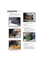
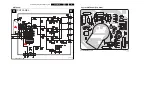
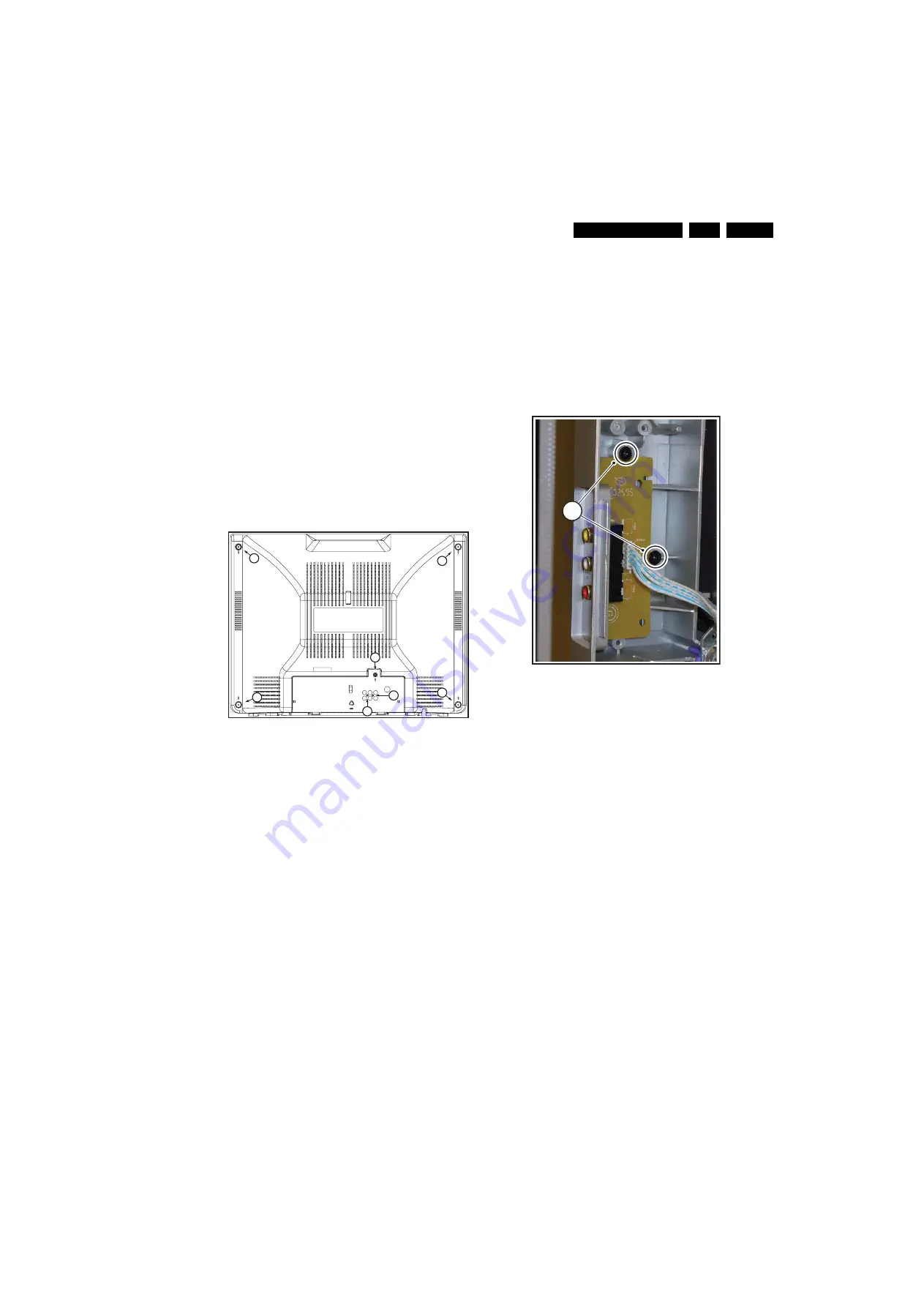
Remove all the fixation screws of the rear cover [1] and [2].
2.
Now, pull the rear cover backwards and remove it.
Figure 4-1 Rear Cover removal (SL5 styling)
4.2
Assy / Board Removal
Sometimes, it can be necessary to swap a complete assy or
Printed Wiring Board (PWB). How that can be done is
explained below.
4.2.1
Side IO/Keyboard Panel Removal
1.
Remove the fixation screws [3].
2.
Remove the module from the TV.
Figure 4-2 Side-IO/Keyboard panel removal (SL5 styling)
H_17130_036.eps
070507
2
1
1
1
1
1
2
H_171
3
0_040.ep
s
070507
1
3


