Service Modes, Error Codes, and Fault Finding
EN 14
TES1.0E LA
5.
5.
Service Modes, Error Codes, and Fault Finding
Index of this chapter:
5.1 Service Mode
5.2 Error Codes
5.3 Fault Finding and Repair Tips
5.1
Service Mode
The Service Mode is activated by pressing ‘1923’ on the
Remote Control, while the set is in the Main User Menu.
The software provides menu flexibility and full control to the
software. Service persons can adjust the TV in all manners. In
the Service Menu, you find a list of parameters.
All functions of the Service Mode, and the default parameter
settings, are listed in Chapter “Alignments”.
5.2
Error Codes
These sets do not generate Error Codes
5.3
Fault Finding and Repair Tips
Notes:
•
It is assumed that the components are mounted correctly
with correct values and no bad solder joints.
•
Before any fault finding actions, check if the correct options
are set.
•
The Service Menu contains some useful tests, e.g. “ADE
pattern” in de “Scaler Setup” Menu, that generates
patterns.
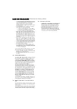
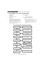
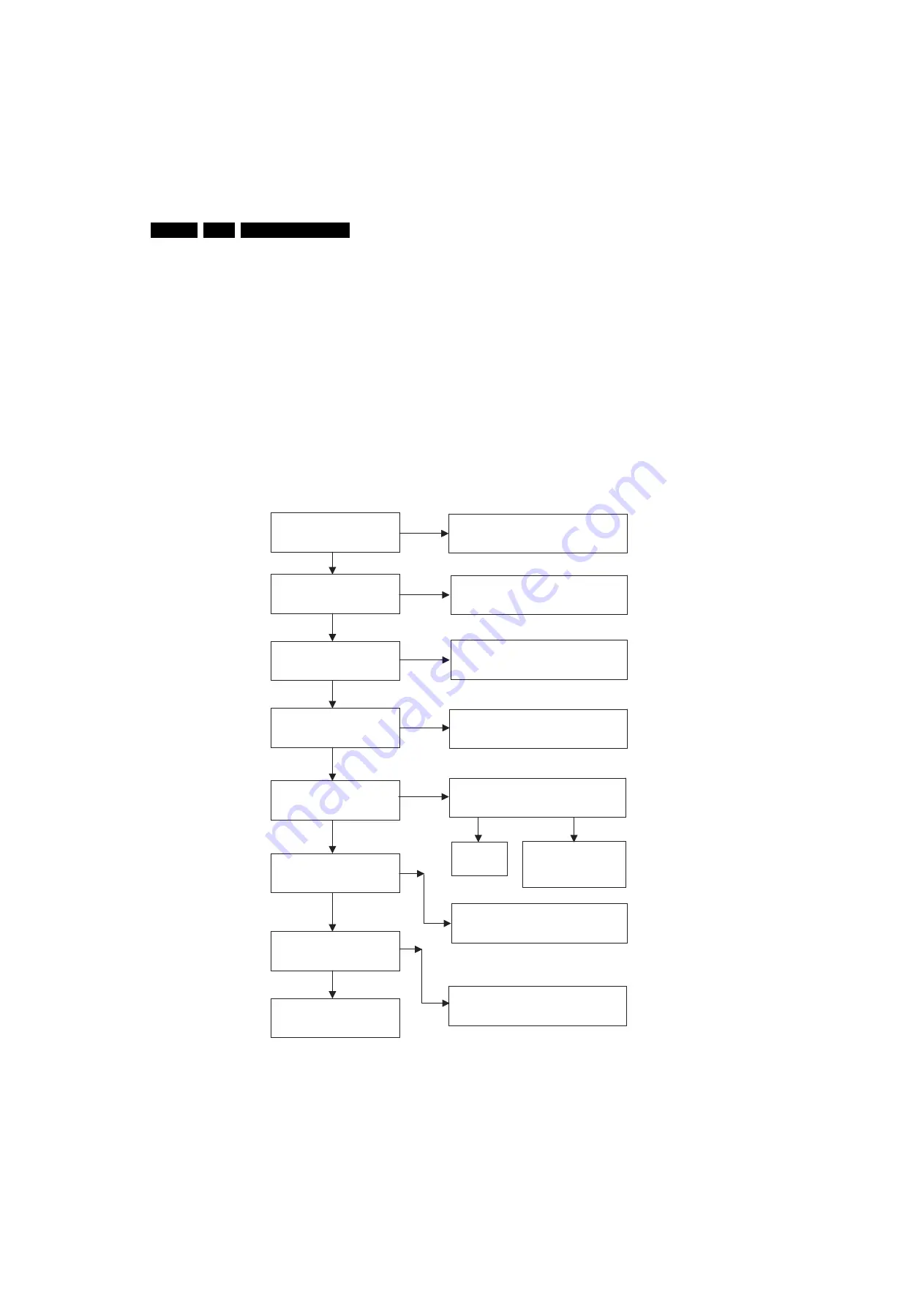
Figure 5-1 Fault finding power supply
Check 220 V AC M
a
in
s
Check C
3
24 Volt
a
ge
Check 5V
S
TBY
Check
3
.
3
V
S
a
nd 1.
8
V
S
Check 5V MAIN
Check 24V,
33
V,12V
8
V,+16V,-16V
Check
3
.
3
V
a
nd 1.
8
V
POWER I
S
OK
FAULT TRACING DIAGRAM FOR POWER
S
UPPLY
NO
NO
NO
NO
NO
NO
NO
YE
S
YE
S
YE
S
YE
S
YE
S
YE
S
YE
S
Check AC Power C
ab
le i
s
Pl
u
gged
Check F
3
00 F
us
e
Check IC21
a
nd Peripher
a
l
Component
s
Check U902
a
nd U90
3
Check
S
t
a
ndBy Pin
Check U900
a
nd U901
HIGH
LOW
S
t
a
ndBy
Mode
Norm
a
l Mode
Check Component
s
For 5V
Check Rel
a
ted Component
s
for
Defective O
u
tp
u
t
s
G_16510_052.ep
s
211106


