M
AINTENANCE
P
ROCEDURES
: T
ILT
M
OTOR
A
SSEMBLY
/ T
ILT
E
NCODER
/ T
ILT
B
ELT
R
EMOVAL
0 2 . 9 6 8 7 . 0 0 1 0 0
35
2
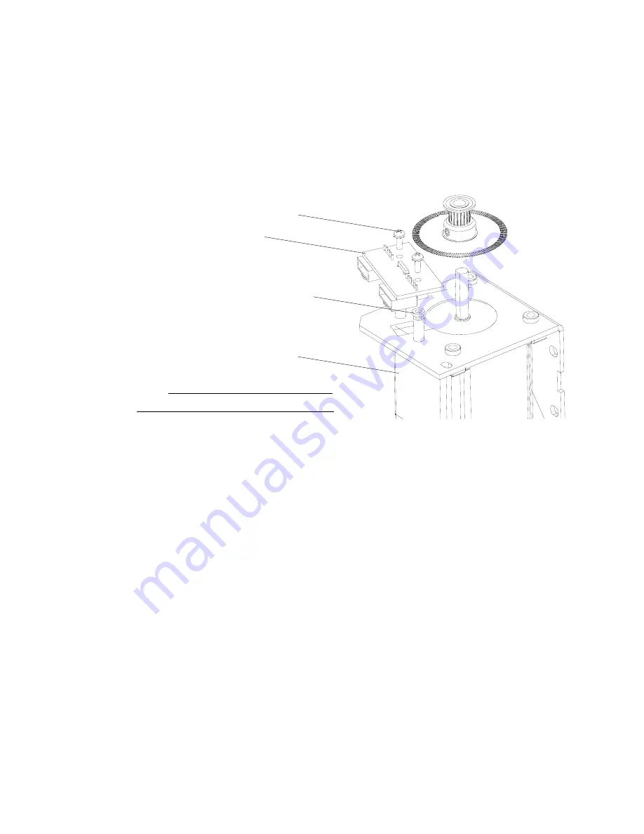
To remove tilt encoder
Step
1. Remove tilt motor assembly following procedure in
“Tilt Motor Assembly / Tilt Encoder /
Step
2. Remove two 4-40 x 1/4" PPG SEMS screws and associated nylon spacers and remove Tilt
Encoder PCB.
Step
3. Reassemble following steps in reverse order.
To remove tilt belt:
Step
1. Remove tilt motor assembly following procedure in
“Tilt Motor Assembly / Tilt Encoder /
Step
2. Disconnect all wiring coming through tilt belt side tilt tube, from inside head assembly.
Step
3. Cut any cable ties required
Step
4. Carefully, pull wiring through tilt belt.
Step
5. Remove tilt belt.
Step
6. Reassemble following steps in reverse order.
NOTE:
Components removed and exploded for clarity.
Tilt Motor
Assembly
Tilt Encoder PCB
Nylon Spacer (x2)
4-40 x 1/4" PPB
SEMS Screw (x2)
Summary of Contents for Vari-Lite VL770
Page 1: ......
Page 13: ...FOREWORD 02 9687 0010 0 xi ...
Page 14: ...VARI LITE VL440 VL770 VL880 SPOT LUMINAIRES SERVICE MANUAL xii 02 9687 0010 0 ...
Page 30: ...VARI LITE VL440 VL770 VL880 SPOT LUMINAIRES SERVICE MANUAL 12 02 9687 0010 0 Notes ...
Page 156: ...VARI LITE VL440 VL770 VL880 SPOT LUMINAIRES SERVICE MANUAL 138 02 9687 0010 0 Notes ...
Page 164: ...VARI LITE VL440 VL770 VL880 SPOT LUMINAIRES SERVICE MANUAL 146 02 9687 0010 0 Notes ...
Page 188: ...VARI LITE VL440 VL770 VL880 SPOT LUMINAIRES SERVICE MANUAL 170 02 9687 0010 0 Notes ...
Page 189: ......


