
88
Pick-up element
1/3" solid state CCD
Pixel elements 5
12 (H) x 582 (V), PAL interlaced, or 512(H) x 492 (V), NTSC
interlaced
Resolution 330
TVL
Gain control
automatic
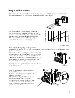
Lens
See: Using a different lens
Iris Electronic
iris
When connected, an auto-iris lens overrides the electronic iris.
Light sensitivity
• 0.3 lux minimally acceptable picture with standard lens (F1.2)
at 3200K, transmission 86%, scene reflection 100%
• 0.5 lux, 50ire (-6dB) with standard lens (F1.2) at 3200K,
transmission 86%, scene reflection 100%
Scene illumination
Not for continuous use above 2k lux with standard lens (F1.2)
For outdoor use an auto-iris lens is recommended.
Signal to noise ratio
48dB at 200-25000 lux, 25°C
White balance TTL
range 2500-6500K
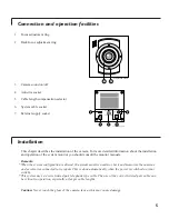
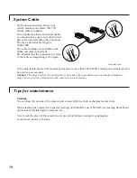
System connector (output)
RJIIE plug
Microphone
Built-in, can be switched off at the camera.
• Frequency range
300-3000Hz
Synchronisation
The camera automatically synchronises to the system monitor.
Power supply
24VDC, when the system-cable length exceeds 200m/600ft a power-
adapter (24VDC, current limit 500mA) is required (available as
accessory)
Power consumption
≤
3W
System-cable length
max. 300m/900ft (when a mains power adaptor is used)
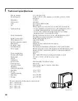
Dimensions
72,5 (H) x 70 (W) x 60 (D) mm (excl. lens)
Weight 190g
Connectors
• System cable
RJ11E modular ("telephone" plug)
• External power
Power jack
Auto-iris control
4-pole socket, passive Auto-iris, direct drive
Mounting
1/4" 20 UNC
Ambient temperature
• Operating
-10 to +50°C
• Storage
-25 to +70°C
Ambient humidity
• Operating
20 to 90% RH
• Storage
up to 99% RH
Technical specifications
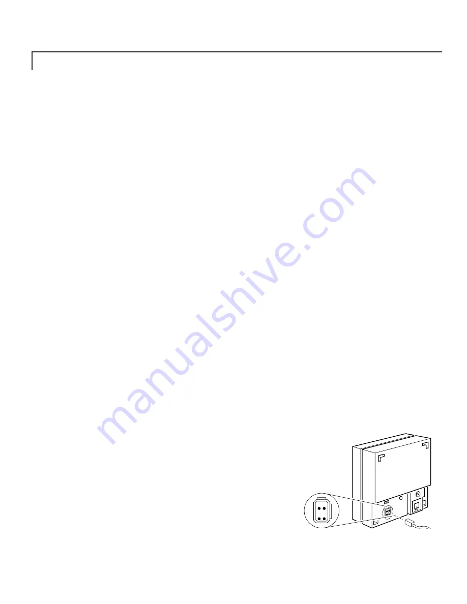
CL 66610005_309.AI
4 2
3 1
The pin connections of the auto-iris connector are:
pin 1 = control coil -
pin 2 = control coil +
pin 3 = drive coil -
pin 4 = drive coil +


