Circuit descriptions and List of abbreviations
GB 107
VR120
9.
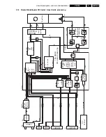
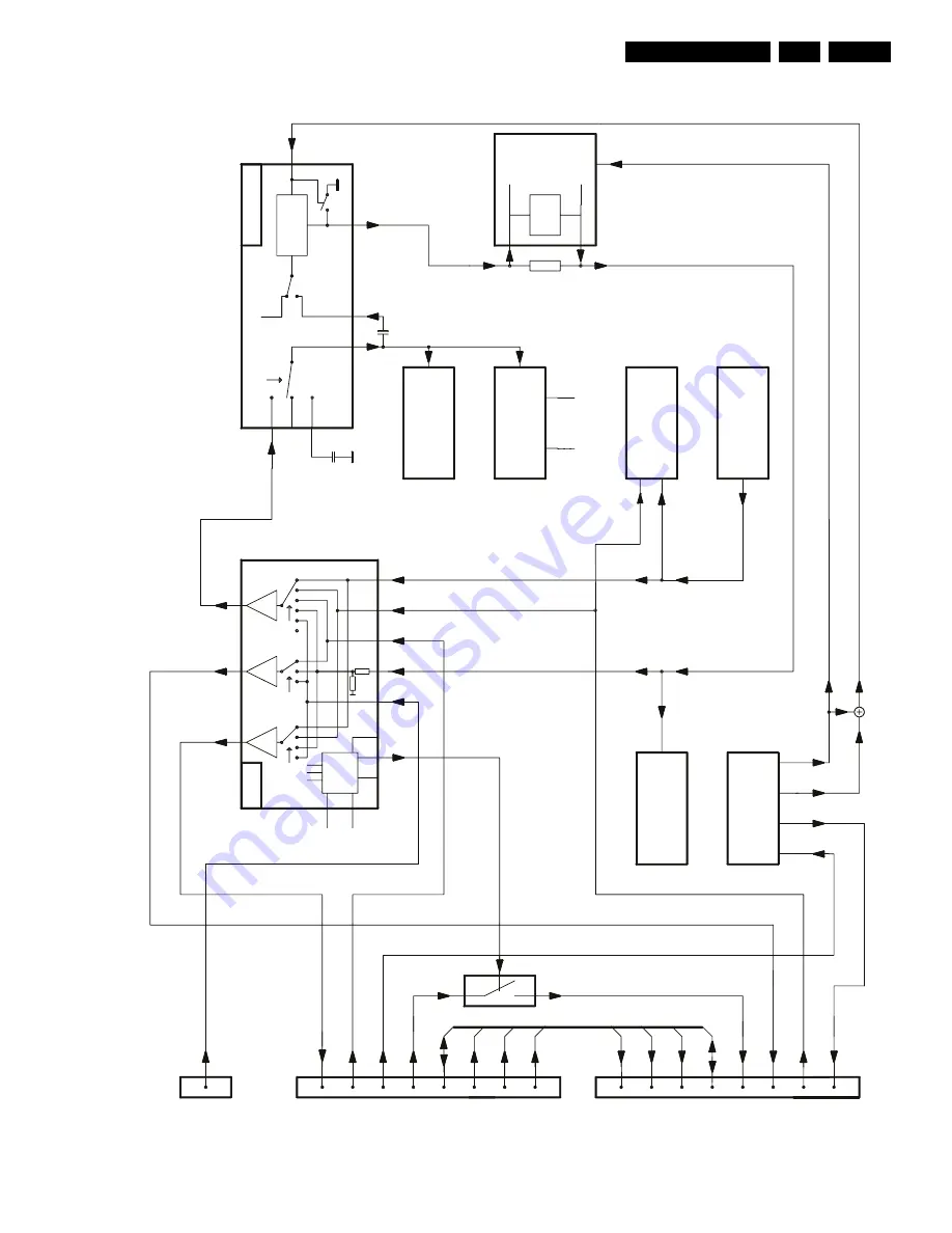
9.12 Simple Blockdiagram
Mute
10k
10k
BUS
x1
x2
x2
VOUT
FF
P
O
F
P
VSB
VOUT
VIN1
VFV
OF
P
not
fo
rVPO
Bypass
Secam
FF
P
VSB
VREC
VREC
5
4
17
18
15
9
VBS
SYCA
Video-
Part
VS
VS_
SEC
7072
75
02
7502
7530
VPS/
PDC
VPO
FO
M
E
FV
LA715
95
M
70
04-B
26
29
31
32
34
36
38
Ge
ne
ra
to
r
Testp
ict.
IN3
IN2
IN1
REC/EE
PLAY
8SC1
8SC2
Switchin
g
Video
In
Video
Ou
t
Blanking
8SC1
CENTRAL CONTROL
FO
ME
VPS/PDC
VOUT1
bla
nkin
g
VIN1
FV
TUMOD
VS-SECAM
0E
no
t
fo
r
OSD
VFV
VFV
VIN1
2
16
15
13
11
9
SDA
SDA
SCL
SCL
from AIO1
fr
om
AIO1
7
51
2
10
8
6
4
STV640
1
IO
7904
Video
fr
om
Fr
on
t
plu
g
1954A
VOUT
VBS
pin
10
re
d
gr
ee
n
blu
e
blu
e
gr
ee
n
re
d
pin
10
Blanking
Switchin
g
Video
In
Video
Ou
t
VFR
VFR
VOUT2
19
7
20
11
8
15
16
10
10
16
15
19
11
20
7
8
Fr
on
t
plu
g
Scart2
Scart1
8SC2
I
C-Bus
2
I
C-Bus
2
IC
2
VOUT1
VOUT2
MON
MON
7913
F
V
17
01
1
AIO1
bla
nkin
g
pin
10
pin
10
VIN2
VIN2
blu
e
gr
ee
n
re
d
blu
e
gr
ee
n
re
d
IO-Block
diagram
2
Scart-V
ideo-Mono&Stereo
MODULA
T
O
R
1952
1951
61
55
32
36
15
VPO
7899-B
LM339D
SDA5650
LA7339A
SDA5652
Summary of Contents for VR570
Page 12: ...Direction for use GB 12 VR120 3 3 Direction for use RT111 RT116 RT112 RT114 RT123 RT121 RT128 ...
Page 15: ...Direction for use GB 15 VR120 3 SAT VR870L VR870CC VR720 Set width 435 mm ...
Page 56: ...Service modes Repair tips GB 56 VR120 5 Engineer s remarks ...
Page 79: ...Circuit diagrams and PWB layouts Wiring diagram 79 VR120 7 7 16 Wiring Diagram Motherboard ...
Page 81: ...Circuit diagrams and PWB layouts Wiring diagram 81 VR120 7 Engineer s remarks ...
Page 82: ...82 VR120 7 Circuit diagrams and PWB layouts Wiring diagram Engineer s remarks ...
Page 83: ...Circuit diagrams and PWB layouts Wiring diagram 83 VR120 7 7 18 Mother board component side ...
Page 119: ...Tape deck GB 119 VR120 10 ...
Page 123: ...Tape deck GB 123 VR120 10 Engineer s remarks ...


