Circuit descriptions and List of abbreviations
GB 109
VR120
9.
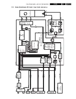
9.13 Simple Blockdiagram FM Audio / Linear Audio processing
TUNER
CINCH
EXT1
EXT2
EXT3
SAP
+15dB
-48dB
mute
+15dB
0dB
mute
L+R
L+R x V
olume
L
R
L x V
olume
AMLR
REC
AMLP
PB
STEREO
LEFT
RIGHT
NORMAL
NOR+ST
NOR+L
NOR+R
mute
EXT2
OutSel
EXT1
TUNER
OutSel
-
mute
-
mute
OutSel
STEREO
CINCH
CINCH
Front
Rear
SCART1
SCART2
TVC
DECK-µC
TDA
9605
H
FM-Audio
Process
ing
LA7159
5M
Linear-A
ud.
Process
ing
InputSel
V
olume
L/R
Lin.Audio
Sel
OutputSel
LineSel
DecoderSel
Mute
Mute
Level
Env-Sel
AFC
ALC
Rec-Amp
EQ-Amp
Line
TDA 98xx
1701
7721
FV
ST/NIC
AF
AL
Tape
Deck
1954-B
IO 1956
IO
IO
DE
FV
7899-B
7760/7761
7650
7004-A
1951
1952
TUMOD
Stereo
Dec.
Demod.
Head
Amplifier
L
R
R
2
2
1
1
R
L
6
12
6
57
35
78
22
96
21
9
11
7
1965-1
1965-3
37
4
44
13
20
17
19
16
8/9
6/7
4/5
2/3
3
3
L
TDA9873
TRIA/DC
L
R
AH1
APH
REC
EtoE
PB
AOUT2L
AIN2L
AOUT1L
AIN1L
AINFL
AFL
AFR
AMCO
AMCO
AOUT2R
AIN2R
AOUT1R
AIN1R
AINFR
AH2
ARH
FMAudio
Processing
MSP3415
Nicam
SIF2
3
17
36
10
AHC
Summary of Contents for VR570
Page 12: ...Direction for use GB 12 VR120 3 3 Direction for use RT111 RT116 RT112 RT114 RT123 RT121 RT128 ...
Page 15: ...Direction for use GB 15 VR120 3 SAT VR870L VR870CC VR720 Set width 435 mm ...
Page 56: ...Service modes Repair tips GB 56 VR120 5 Engineer s remarks ...
Page 79: ...Circuit diagrams and PWB layouts Wiring diagram 79 VR120 7 7 16 Wiring Diagram Motherboard ...
Page 81: ...Circuit diagrams and PWB layouts Wiring diagram 81 VR120 7 Engineer s remarks ...
Page 82: ...82 VR120 7 Circuit diagrams and PWB layouts Wiring diagram Engineer s remarks ...
Page 83: ...Circuit diagrams and PWB layouts Wiring diagram 83 VR120 7 7 18 Mother board component side ...
Page 119: ...Tape deck GB 119 VR120 10 ...
Page 123: ...Tape deck GB 123 VR120 10 Engineer s remarks ...

