Tape deck
GB 113
VR120
10.
10. Tape deck
10.1 Drive assembly
This tape deck has three motors; one providing precision
drive for the scanner unit; the second providing direct drive
for the capstan and belt drive for the reel tables; the third
motor drives the lift and tape threading/dethreading
operations.
Special features are:
–
Quick start
–
Short winding time
–
Automatic cleaning of video heads by cleaning roller
To obtain a high repair standard we have developped a
range of service kit’s. These kit’s covers the spare parts
which are engaged together.
The tape deck’s sensors are located on the motherboard
underneath the tape deck, and included in its circuitry, lay out
and parts list.
10.1.1 Deck parts replacement
The procedure for the removal and refitting of the following
parts is described; only the lift, the scanner, the capstan
motor and the A/C head are fixed by screws.
All the other deck assembly parts are held only by snap
hooks.
For the replacement of parts on the underside of the tape
deck, remove the tape deck from the motherboard.
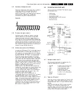
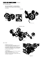
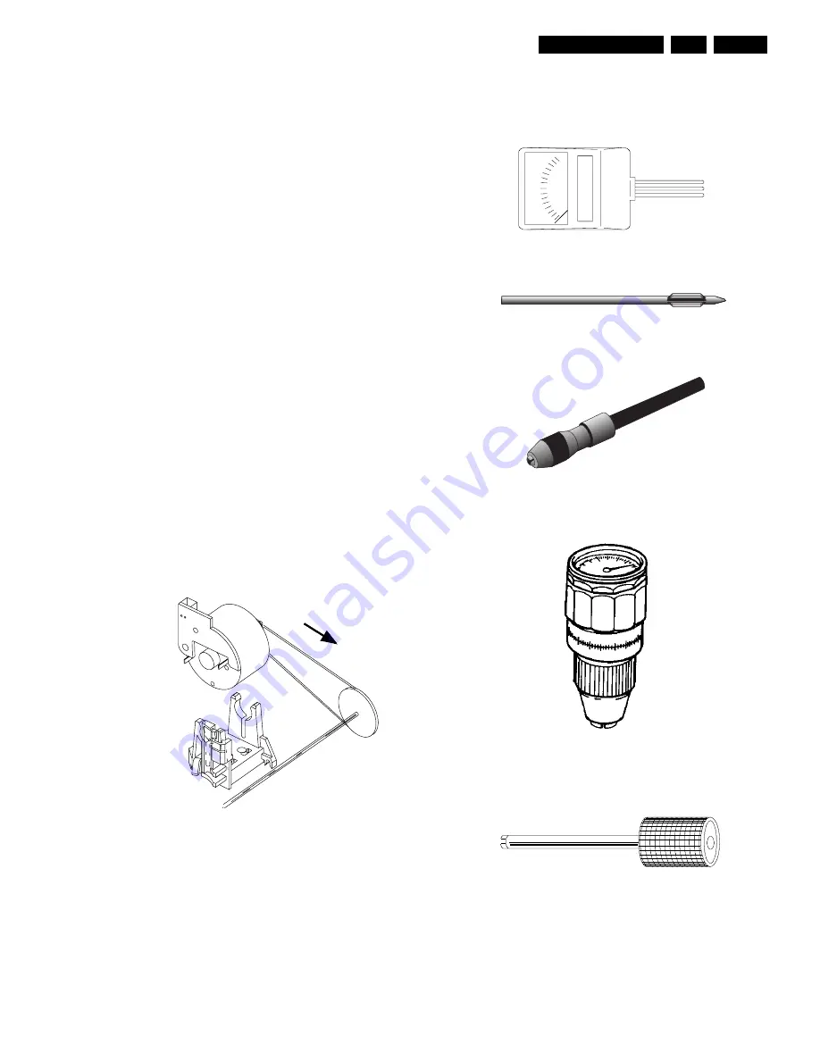
Manual extraction of cassette:
If, after the Eject button has been pressed, the drive does not
unthread and eject the cassette, the dethreading/eject
operation can also be carried out manually by turning the
wheel at the rear of the threading motor.
Figure 10-1
IMPORTANT:
After each repair has been carried out in the drive assembly,
the first operation after repairing must be to bring the
cassette compartment into „eject“ position by hand.
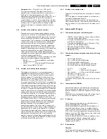
Auxiliary tools for deck adjustment:
Testcassette 4822 397 30103
Nylon gloves 5322 395 94022
T e n t e l o m e t e r
Tentelometer 4822 395 90584
Tool for tapetension adjustment 4822 395 50188
Handle 4822 256 90493
Torquemeter:
600 gf-cm 4822 395 90232
90 gf-cm 4822 395 80196
Post adjustment screwdriver 4822 395 50275
Summary of Contents for VR570
Page 12: ...Direction for use GB 12 VR120 3 3 Direction for use RT111 RT116 RT112 RT114 RT123 RT121 RT128 ...
Page 15: ...Direction for use GB 15 VR120 3 SAT VR870L VR870CC VR720 Set width 435 mm ...
Page 56: ...Service modes Repair tips GB 56 VR120 5 Engineer s remarks ...
Page 79: ...Circuit diagrams and PWB layouts Wiring diagram 79 VR120 7 7 16 Wiring Diagram Motherboard ...
Page 81: ...Circuit diagrams and PWB layouts Wiring diagram 81 VR120 7 Engineer s remarks ...
Page 82: ...82 VR120 7 Circuit diagrams and PWB layouts Wiring diagram Engineer s remarks ...
Page 83: ...Circuit diagrams and PWB layouts Wiring diagram 83 VR120 7 7 18 Mother board component side ...
Page 119: ...Tape deck GB 119 VR120 10 ...
Page 123: ...Tape deck GB 123 VR120 10 Engineer s remarks ...

