Tape deck
GB 115
VR120
10.
10.1.4 Scanner replacement
Removal:
Nylon gloves should be worn when handling the head disc.
Remove the deck from the set/mobo.
Unscrew the three scanner screws on the underside of the
deck.
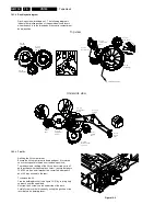
Pull out the scanner from the top. ( see figure 10-3 )
Figure 10-3
Installation:
Insert the scanner (with protective cover) carefully from top.
PCB and flex foil to the rear.
Be shure that the scanner is engaged to the referenc pin
located on the chassis.
Turn the tape deck, holding the scanner in the deck by hand
and fix it by use of the tree scanner screws.
Remove carefully the protective cover from top.
After replacing the scanner, carry out the following
adjustments and checks:
Head switching puls.
Writing current adjustment.
Tape path alignment.
Check and adjust if necessary.
10.1.5 A/C Head (Combi head) (Pos. 36)
Remove the fixing spring (A) ( see figure 10-4 )
Remove the fixing screw and replace the A/C head.
Use a new fixing spring (included with new A/Chead) for
reassembly.
After the A/C head has been replaced, all adjustments
described in paragraph “A/C Combi head” and paragraph
10.2.2 have to be carried out.
Figure 10-4
10.1.6 Threading motor (Pos. 38)
Remove the belt and disconnect the connector plug.
Remove the threading motor from the motor supports ( see
figure 10-5 ).
During reassembly ensure that the threading motor is
correctly located in the front and rear supports.
Figure 10-5
10.1.7 Capstan motor (Pos. 127)
Remove the tape deck.
Remove the belt (pos.126) on the underside;
Remove the three capstan motor fixing screws ( see figure
10-6 ) and withdraw the capstan motor downward from the
drive assy.
The reassembly is carried out in reverse order. Make sure
that the capstan is free of grease.
Figure 10-6
Top view
Scanner screws
(3 pcs.)
Underside view
height screw
azimut screw
tilt screw
fixing screw
A
chassis
capstanmotor
Summary of Contents for VR570
Page 12: ...Direction for use GB 12 VR120 3 3 Direction for use RT111 RT116 RT112 RT114 RT123 RT121 RT128 ...
Page 15: ...Direction for use GB 15 VR120 3 SAT VR870L VR870CC VR720 Set width 435 mm ...
Page 56: ...Service modes Repair tips GB 56 VR120 5 Engineer s remarks ...
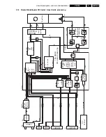
Page 79: ...Circuit diagrams and PWB layouts Wiring diagram 79 VR120 7 7 16 Wiring Diagram Motherboard ...
Page 81: ...Circuit diagrams and PWB layouts Wiring diagram 81 VR120 7 Engineer s remarks ...
Page 82: ...82 VR120 7 Circuit diagrams and PWB layouts Wiring diagram Engineer s remarks ...
Page 83: ...Circuit diagrams and PWB layouts Wiring diagram 83 VR120 7 7 18 Mother board component side ...
Page 119: ...Tape deck GB 119 VR120 10 ...
Page 123: ...Tape deck GB 123 VR120 10 Engineer s remarks ...

