Tape deck
GB 118
VR120
10.
10.2.3 Brake band and tape tension
Due to further development it is no longer necessary to make
theseadjustments after replacement of the brake band.
If the brake band or tape tension are completely misadjusted,
set them to a center position; set the drive to „play“ and adjust
the brake band until the edge of the elbow of the tape tension
arm is aligned with the left inner edge of the left guide ( see
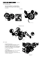
figure 10-13 ).
Figure 10-13
10.2.4 Friction clutch control check
Set the drive to „Play“ position.
Place the torquemeter on the right reel.
Turn the capstan motor to move the right reel clockwise.
Keep turning, until the indication at the torquemeter no longer
changes ( see figure 10-14 ).
The torque has to be 10,5 mNm +/-25% (1/-25%)
10.2.5 Reverse brake control
Set the drive to „Reverse“ position.
Place a torquemeter on the right reel and turn the latter
counterclockwise, until the reel just starts to flip.
The value indicated at the torquemeter has to be 7mNm +/-
3mNm (70 gFcm +/-30gFcm) ( see figure 10-14 ).
Figure 10-14
Guiding left
tension arm
Brakeband adjusting
Tapetension adjustment
Lift assy
Pos. 150
Summary of Contents for VR570
Page 12: ...Direction for use GB 12 VR120 3 3 Direction for use RT111 RT116 RT112 RT114 RT123 RT121 RT128 ...
Page 15: ...Direction for use GB 15 VR120 3 SAT VR870L VR870CC VR720 Set width 435 mm ...
Page 56: ...Service modes Repair tips GB 56 VR120 5 Engineer s remarks ...
Page 79: ...Circuit diagrams and PWB layouts Wiring diagram 79 VR120 7 7 16 Wiring Diagram Motherboard ...
Page 81: ...Circuit diagrams and PWB layouts Wiring diagram 81 VR120 7 Engineer s remarks ...
Page 82: ...82 VR120 7 Circuit diagrams and PWB layouts Wiring diagram Engineer s remarks ...
Page 83: ...Circuit diagrams and PWB layouts Wiring diagram 83 VR120 7 7 18 Mother board component side ...
Page 119: ...Tape deck GB 119 VR120 10 ...
Page 123: ...Tape deck GB 123 VR120 10 Engineer s remarks ...


