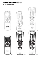
Direction for use
GB 13
VR120
3.
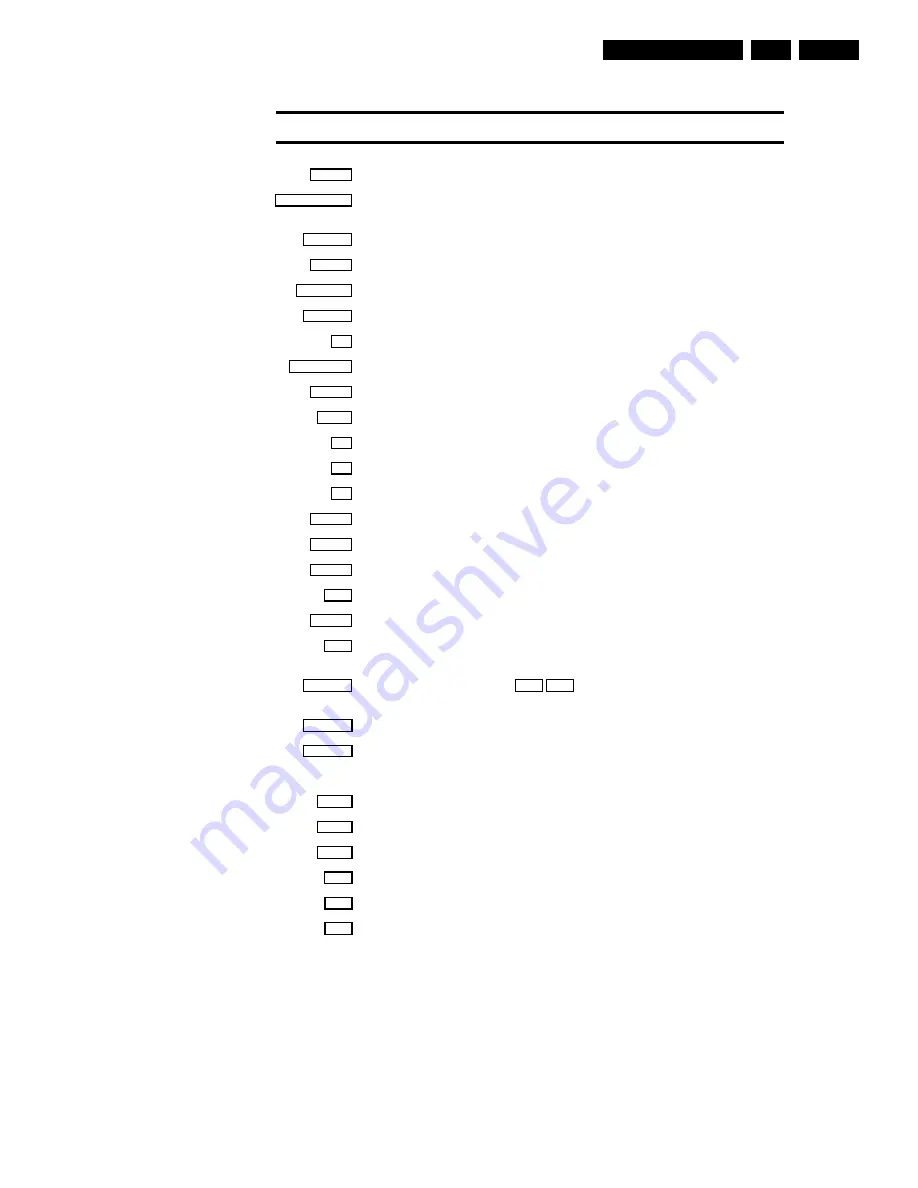
SMART
SMART
: To adjust the picture setting during playback
STANDBY/ON
m
Switch off
: To switch off set, interrupt menu function, interrupt a programmed recording
(TIMER)
CLEAR (CL)
Delete
: To delete last entry/Clear programmed recording (TIMER)
SELECT
Select
: To select a function
CHILD LOCK
Child Lock
: To switch child lock on/off
MONITOR
TV monitor
: To switch between TV reception and VCR playback
0-9
Number buttons
: 0 - 9
TURBO TIMER
TurboTimer
Aufnahmen programmieren mit der Funktion TurboTimer
TIMER
k
TIMER
: To make a manual TIMER programming or to alter or clear a programmed TIMER
MENU
Menu
: To call up or end main menu
OK
Store/Confirm
: To store or confirm entry
Q
Select
: Cursor left
P
Select
: Cursor right
;Pq
Select
: To select a programme number
rP=
Select
: To select a programme number
PLAY
G
Playback
: To play a recorded cassette
H
Rewind
: During STOP and STANDBY: rewind, during PLAYBACK: reverse scanning
STOP
h
Pause/Stop
: To stop the tape, except while a TIMER-recording is being made
I
Forward wind
: During STOP and STANDBY: forward wind, during PLAYBACK: forward
scanning
INDEX
E
Index search
: In combination with
H
/
I
: to search for previous or next recording
on the cassette.
RECORD
n
Record
: To record the programme selected
STILL
R
Still picture
: To stop the tape and show a still picture
Additional TV functions
Sq
TV volume
: TV volume up
Sr
TV volume
: TV volume down
TV
y
TV sound off
: To switch the sound on or off
TV
m
Switch off
: To switch off the TV
TV
q
TV Programme number
: TV programme number up
TV
r
TV Programme number
: TV programme number down
Remote control
Summary of Contents for VR570
Page 12: ...Direction for use GB 12 VR120 3 3 Direction for use RT111 RT116 RT112 RT114 RT123 RT121 RT128 ...
Page 15: ...Direction for use GB 15 VR120 3 SAT VR870L VR870CC VR720 Set width 435 mm ...
Page 56: ...Service modes Repair tips GB 56 VR120 5 Engineer s remarks ...
Page 79: ...Circuit diagrams and PWB layouts Wiring diagram 79 VR120 7 7 16 Wiring Diagram Motherboard ...
Page 81: ...Circuit diagrams and PWB layouts Wiring diagram 81 VR120 7 Engineer s remarks ...
Page 82: ...82 VR120 7 Circuit diagrams and PWB layouts Wiring diagram Engineer s remarks ...
Page 83: ...Circuit diagrams and PWB layouts Wiring diagram 83 VR120 7 7 18 Mother board component side ...
Page 119: ...Tape deck GB 119 VR120 10 ...
Page 123: ...Tape deck GB 123 VR120 10 Engineer s remarks ...


