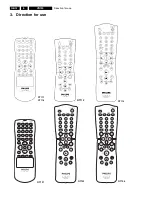
Direction for use
GB 17
VR120
3.
B
Connecting
the
video
recorder
Preparing
the
remote
control
for
operation
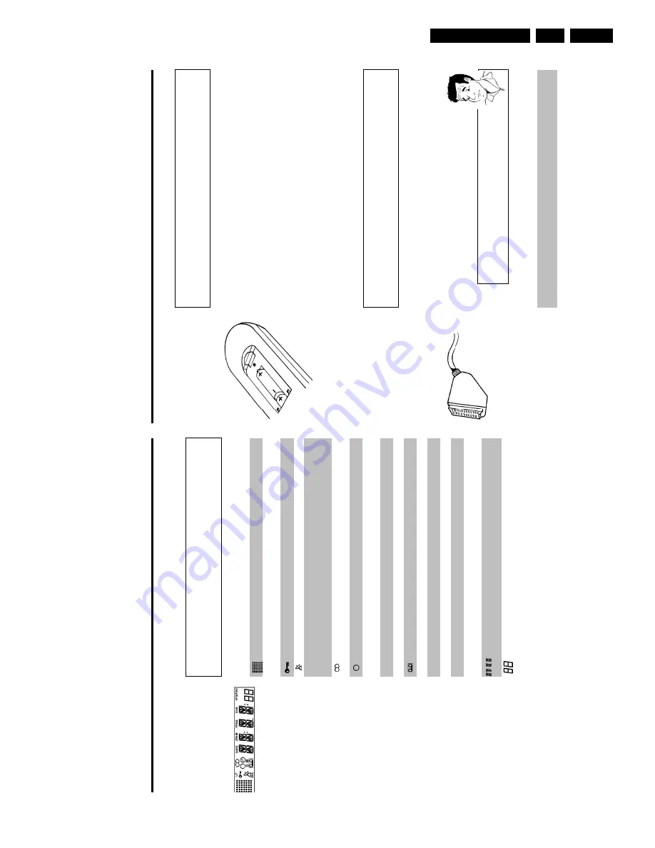
The
remote
control
and
its
batteries
are
packed
separately
in
the
original
video
recorder
packaging.
You
must
install
the
batteries
in
the
remote
control
before
use
-
described
in
the
following
section.
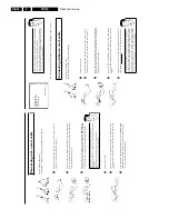
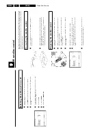
1
Take
the
remote
control
and
the
enclosed
batteries
(2
batteries).
2
Open
the
remote
control's
battery
compartment
and
place
the
batteries
in
it
as
shown
in
the
picture
and
close
the
battery
compartment.
The
remote
control
is
now
ready
to
use.
Its
range
is
approximately
5
meters.
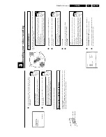
Connecting
your
video
recorder
to
the
TV
set
The
necessary
cable
connections
must
be
made
before
you
can
record
or
playback
TV
programmes
using
your
video
recorder.
We
recommend
that
you
use
a
scart
cable
to
connect
your
TV
set
and
video
recorder.
What
is
a
scart
cable?
The
scart
or
Euro
AV
cable
serves
as
the
universal
connector
for
picture,
sound
and
control
signals.
With
this
type
of
connection,
there
is
practically
no
loss
of
quality
during
the
picture
or
sound
transfer.
When
you
install
your
video
recorder
for
the
first
time,
select
one
of
the
following
options:
'Connecting
with
a
scart
cable'
If
your
TV
set
has
a
scart
socket
and
you
are
using
a
scart
cable.
'Connecting
without
a
scart
cable'
If
you
do
not
wish
to
use
a
scart
cable.
The
symbols
on
your
video
recorder
display
These
symbols
can
light
up
on
your
video
recorder
display:
This
is
where
the
current
operating
mode
is
shown
as
a
symbol.
LP
When
you
have
switched
on
the
LP
(Long
Play)
function
or
when
you
play
a
tape
that
has
been
recorded
in
LP
(Long
Play).
When
you
have
switched
on
the
child
lock.
When
a
satellite
recording
has
been
programmed.
DEC
When
a
decoder
has
been
allocated
to
the
TV
channel
(currently
selected
programme
number
on
the
video
recorder)
you
have
currently
selected
on
the
video
recorder.
When
you
play
a
cassette
that
has
been
recorded
with
hifi
sound,
or
when
a
hifi
sound
is
transmitted.
When
you
are
making
a
recording.
k
When
you
have
programmed
a
recording
or
when
a
programmed
recording
is
being
made.
D
When
you
are
programming
daily
recordings.
W
When
you
are
programming
weekly
recordings.
When
you
have
put
a
cassette
in
the
video
recorder.
DATE
When
the
date
of
the
programmed
recording
is
shown.
START
When
the
start
time
of
the
programmed
recording
is
shown.
PROG.
When
the
programme
number
of
the
programmed
recording
is
shown.
END
When
the
end
time
of
the
programmed
recording
is
shown.
VPS/PDC
Video
Programming
System
/
Programme
Delivery
Control:
when
a
VPS
or
PDC
code
is
being
transmitted.
Display
of
programme
number
of
the
TV
channel
/
tape
position
/
channel
name
/
function.
Tape
position
in
seconds.
Summary of Contents for VR570
Page 12: ...Direction for use GB 12 VR120 3 3 Direction for use RT111 RT116 RT112 RT114 RT123 RT121 RT128 ...
Page 15: ...Direction for use GB 15 VR120 3 SAT VR870L VR870CC VR720 Set width 435 mm ...
Page 56: ...Service modes Repair tips GB 56 VR120 5 Engineer s remarks ...
Page 79: ...Circuit diagrams and PWB layouts Wiring diagram 79 VR120 7 7 16 Wiring Diagram Motherboard ...
Page 81: ...Circuit diagrams and PWB layouts Wiring diagram 81 VR120 7 Engineer s remarks ...
Page 82: ...82 VR120 7 Circuit diagrams and PWB layouts Wiring diagram Engineer s remarks ...
Page 83: ...Circuit diagrams and PWB layouts Wiring diagram 83 VR120 7 7 18 Mother board component side ...
Page 119: ...Tape deck GB 119 VR120 10 ...
Page 123: ...Tape deck GB 123 VR120 10 Engineer s remarks ...


