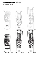
Direction for use
GB 18
VR120
3.
CONGRATULATIONS
YOU
NOW
OWN
A
NEW
PHILIPS
VIDEO
RECORDER
CONTINUEpOK
a
My
screen
is
empty
b
Many
TV
sets
are
switched
to
the
programme
number
for
the
scart
socket
by
way
of
a
control
signal
sent
through
the
scart
cable.
b
If
the
TV
set
does
not
automatically
switch
to
the
scart
socket
programme
number,
manually
change
to
the
corresponding
programme
number
on
your
TV
set
(see
your
TV's
operating
instructions).
Then,
read
the
paragraph
'Initial
installation'
in
the
chapter
'Installing
your
video
recorder'.
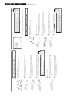
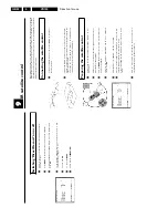
Connecting
without
a
scart
cable
Have
the
following
cables
ready:
an
aerial
cable
(1,
supplied),
a
mains
cable
(2,
supplied).
1
Switch
off
your
TV
set.
2
Remove
the
aerial
cable
plug
from
the
aerial
input
socket
of
the
TV
set.
Insert
it
into
the
socket
2
at
the
back
of
the
video
recorder.
3
Insert
one
end
of
the
supplied
aerial
cable
into
the
socket
3
at
the
back
of
the
video
recorder
and
the
other
end
into
the
aerial
input
socket
at
the
back
of
the
TV
set.
4
Insert
one
end
of
the
supplied
mains
cable
into
the
mains
socket
4
at
the
back
of
the
video
recorder
and
the
other
end
into
the
wall
socket.
5
Switch
on
your
TV
set
and
select
the
programme
number
used
for
video
playback
on
your
TV
set
(see
your
TV's
operating
instructions).
Which
programme
number
is
used
for
video
recorder
operation?
To
ensure
the
stability
of
the
television
picture
during
cassette
playback
(prevention
of
waves
or
streaks),
special
programme
numbers
have
been
set
aside
on
the
TV
for
the
use
of
video
recorders.
This
is
usually
the
highest
possible
programme
number,
e.g.
'12',
'16',
'99'
or
even
programme
number
'0'.
For
more
information,
please
see
your
TV's
operating
instructions.
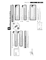
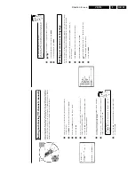
Connecting
with
a
scart
cable
Have
the
following
cables
ready:
an
aerial
cable
(1,
supplied),
a
mains
cable
(2,
supplied),
a
scart
cable
(3).
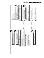
1
Remove
the
aerial
cable
plug
from
your
TV
set.
Insert
it
into
the
socket
2
at
the
back
of
the
video
recorder.
2
Insert
one
end
of
the
supplied
aerial
cable
into
the
socket
3
at
the
back
of
the
video
recorder
and
the
other
end
into
the
aerial
input
socket
at
the
back
of
the
TV
set.
3
Plug
one
end
of
a
scart
cable
into
the
scart
socket
EXT.1
AV
1
at
the
back
of
the
video
recorder
and
the
other
end
into
the
suitable
scart
socket
on
your
TV
set
(see
your
TV's
operating
instructions).
My
TV
set
has
several
scart
sockets.
Which
one
should
I
use?
Select
that
scart
socket
which
is
suited
for
the
video
output
as
well
as
for
the
video
input.
My
TV
offers
me
a
selection
menu
for
the
scart
socket.
Select
'TV'
as
a
connection
source
of
this
scart
socket.
4
Switch
on
the
TV
set.
5
Insert
one
end
of
the
supplied
mains
cable
into
the
mains
socket
4
at
the
back
of
the
video
recorder
and
the
other
end
into
the
wall
socket.
6
If
the
connection
was
properly
made
and
your
TV
was
automatically
switched
to
the
programme
number
for
the
scart
socket,
e.g.
'EXT',
'0',
'AV',
you
will
see
the
following
picture:
Summary of Contents for VR570
Page 12: ...Direction for use GB 12 VR120 3 3 Direction for use RT111 RT116 RT112 RT114 RT123 RT121 RT128 ...
Page 15: ...Direction for use GB 15 VR120 3 SAT VR870L VR870CC VR720 Set width 435 mm ...
Page 56: ...Service modes Repair tips GB 56 VR120 5 Engineer s remarks ...
Page 79: ...Circuit diagrams and PWB layouts Wiring diagram 79 VR120 7 7 16 Wiring Diagram Motherboard ...
Page 81: ...Circuit diagrams and PWB layouts Wiring diagram 81 VR120 7 Engineer s remarks ...
Page 82: ...82 VR120 7 Circuit diagrams and PWB layouts Wiring diagram Engineer s remarks ...
Page 83: ...Circuit diagrams and PWB layouts Wiring diagram 83 VR120 7 7 18 Mother board component side ...
Page 119: ...Tape deck GB 119 VR120 10 ...
Page 123: ...Tape deck GB 123 VR120 10 Engineer s remarks ...

