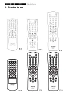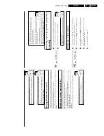
Direction for use
GB 19
VR120
3.
C
Installing
your
video
recording
Initial
installation
This
chapter
shows
you
how
to
start
the
initial
installation.
The
video
recorder
automatically
seeks
out
and
stores
all
available
TV
channels.
'Aim'
correctly
In
the
following
sections,
you
require
the
remote
control
for
the
first
time.
When
using,
always
aim
the
front
of
the
remote
control
at
the
video
recorder
and
not
at
the
TV
set.
Connecting
additional
devices
After
you
have
connected
additional
devices
(satellite
receiver,
etc.)
through
the
aerial
cable,
switch
them
on.
The
automatic
channel
search
will
recognise
them
and
save
them.
1
Confirm
the
image
on
the
TV
screen
by
pressing
the
OK
button
on
the
remote
control.
2
Select
the
desired
language
for
the
on-screen
menu
by
pressing
P
r=
or
;q
P
.
What
is
an
on/screen
menu?
The
multi-language
on-screen
menu
takes
the
mystery
out
of
using
your
new
video
recorder.
All
settings
and/or
functions
are
displayed
on
your
TV
screen
in
the
corresponding
language.
3
Confirm
with
OK
.
4
Select
the
country
of
your
residence
with
P
r=
or
;q
P
.
If
your
country
does
not
appear,
select
'
OTHERS
'.
Confirm
with
OK
.
a
The
video
recorder
does
not
find
any
TV
channels
during
the
search
b
Select
channel
1
o
n
the
TV
set.
Can
you
see
the
saved
TV
channel
on
the
TV
set?
If
not,
check
the
cable
connection
of
the
aerial
(aerial
socket),
video
recorder,
TV
set.
b
Please
have
patience.
The
video
recorder
searches
the
entire
frequency
range
in
order
to
find
and
save
the
largest
possible
number
of
TV
channels.
It
is
possible
that
the
TV
channels
in
your
country
are
broadcast
in
a
higher
frequency
range.
As
soon
as
this
range
is
reached
during
the
search,
the
video
recorder
will
find
the
TV
channels.
CLOCK
YEAR
è
2001
p
MONTH
01
DATE
01
TIME
20:00
SMART
CLOCK
ON
________________________________
EXITpMENU
STOREpOK
5
When
the
automatic
TV
channel
search
is
complete,
'
STORED
'
will
briefly
appear
on
the
TV
screen.
'
YEAR
',
'
MONTH
',
'
DATE
',
'
TIME
'
will
appear
on
the
TV
screen.
6
Check
the
year
in
line
'
YEAR
'.
If
required,
please
change
the
year
with
the
number
buttons
0-9
on
the
remote
control.
6
Select
this
programme
number
and
manually
start
the
TV's
channel
search
as
if
you
wanted
to
save
a
new
TV
channel
until
the
'test
image'
appears.
CONGRATULATIONS
YOU
NOW
OWN
A
NEW
PHILIPS
VIDEO
RECORDER
CONTINUEpOK
a
I
d
o
not
see
a
'test
screen'
b
Check
the
cable
connections.
b
The
video
recorder
'transmits'
on
the
591MHz
frequency
(channel
36)
Repeat
the
channel
search
on
your
TV
set.
7
Save
this
programme
number
setting
on
your
TV
set
for
video
recorder
operation.
Programme
number
for
video
recorder
operation
You
have
now
saved
a
programme
number
for
use
by
your
video
recorder
as
you
would
a
regular
TV
channel.
This
programme
number
must
now
be
used
in
future
for
video
recorder
playback
('video
recorder'
TV
channel).
You
can
find
more
details
in
chapter
'Initial
Installation'.
Connecting
additional
devices
You
can
connect
additional
devices
such
as
decoders,
satellite
receivers,
camcorders,
etc.
to
the
socket
EXT.2
AV
2
.
Two
audio
sockets
AUDO
OUT
L
R
are
located
on
the
back
of
the
video
recorder
(audio
signal
output
left/right).
These
can
be
used
to
connect
stereo
systems.
Summary of Contents for VR570
Page 12: ...Direction for use GB 12 VR120 3 3 Direction for use RT111 RT116 RT112 RT114 RT123 RT121 RT128 ...
Page 15: ...Direction for use GB 15 VR120 3 SAT VR870L VR870CC VR720 Set width 435 mm ...
Page 56: ...Service modes Repair tips GB 56 VR120 5 Engineer s remarks ...
Page 79: ...Circuit diagrams and PWB layouts Wiring diagram 79 VR120 7 7 16 Wiring Diagram Motherboard ...
Page 81: ...Circuit diagrams and PWB layouts Wiring diagram 81 VR120 7 Engineer s remarks ...
Page 82: ...82 VR120 7 Circuit diagrams and PWB layouts Wiring diagram Engineer s remarks ...
Page 83: ...Circuit diagrams and PWB layouts Wiring diagram 83 VR120 7 7 18 Mother board component side ...
Page 119: ...Tape deck GB 119 VR120 10 ...
Page 123: ...Tape deck GB 123 VR120 10 Engineer s remarks ...


