GB 2
VR120
Contents
Page
Contents
Page
1
List of PWBs, Features, Technical
specifications
3
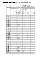
Survey of sets and PWB’s with software versions 3
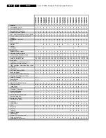
Features
5
Technical specification
9
2
Safety instructions, Modifications
10
Safety instructions
10
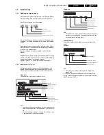
Modifications
11
3
Direction for use
12
Remote control overview
12
Front overview of the sets
14
Direction for use introduction
16
Remote control codes
45
4
Dismantling instructions
46
Dismantling instructions
46
Dismantling of the motherboard/drive
combination
47
Dismantling the drive
48
5
Service modes, Repair tips
49
Special functions
49
Service test program
49
Repair tips
53
6
Block diagrams, Waveforms, Wiring diagram 57
Block diagram Video
57
Block diagram Audio Mono
58
Block diagram Audio Stereo
59
Supply voltages and Bus diagram
60
Supply voltages and Bus diagram
61
Block diagram Central Control
62
Waveforms
63
7
Circuit diagrams and PWB layouts
64
Power supply (PS)
64
Display control (AIO2)
65
Central control (AIO1)
66
Deck control (DE)
67
Variant List Frontend (FV)
68
Frontend (FV)
69
FM stereo (FM-ST)
70
FM Nicam (FM-ST-NIC)
71
Audio Linear (AL) 72
FM - Audio (AF)
73
Video Signal Processing - SECAM (VS-SEC)
74
Video Signal Processing (VS)
75
VPS/PDC & OSD Part (VPO)
76
In/Out Part (IO)
77
FOLLOW ME Part (FOME)
78
Wiring Diagram
79
Mother board - solder side
80
Mother board - component side
83
Connector print (ACP10)
84
Connector print (ACP1)
84
Connector print (QBOE1)
85
Connector print (QBOG1)
85
Connector print (ACP35)
86
Key print (AKP35)
87
Illumination print (AKP13)
88
Key print (AKP36) 89
Shuttle board (ASP10)
89
Shuttle board (QKP21)
89
Test point overview
90
8
Electrical alignments
91
Measuring instruments
91
Setting instructions
91
Video signal processing (VS-SEC)
91
Front End (FV)
92
Deck electronics (DE)
93
Servo System (AIO1)
93
Audio Linear (AL)
94
Display Control (AIO2)
94
9
Circuit descriptions and List of
abbreviations
97
Switched-mode power supply PS (PS Part)
97
Operating unit (DC part)
98
Central Control (AIO part)
99
Deck electronics (DE part)
100
Front end (FV part)
101
Video signal processing VS (VS part)
102
Audio linear (AL part)
104
Audio HiFi - for stereo units (AF part)
105
IN/OUT (IO part)
105
Follow Me (FOME part)
106
VPS/PDC, on-screen display (VPO part)
106
Simple Blockdiagram
107
Simple Blockdiagram FM Audio / Linear Audio
processing
109
List of abbreviations
110
10 Tape deck
113
Drive assembly
113
Adjustments
117
Deck exploded view (TOP)
120
Deck exploded view (BOTTOM)
121
Mechanical parts list
122
11 Exploded views
124
Exploded view set
124
12 Spare parts list
128
Summary of Contents for VR570
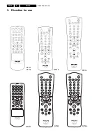
Page 12: ...Direction for use GB 12 VR120 3 3 Direction for use RT111 RT116 RT112 RT114 RT123 RT121 RT128 ...
Page 15: ...Direction for use GB 15 VR120 3 SAT VR870L VR870CC VR720 Set width 435 mm ...
Page 56: ...Service modes Repair tips GB 56 VR120 5 Engineer s remarks ...
Page 79: ...Circuit diagrams and PWB layouts Wiring diagram 79 VR120 7 7 16 Wiring Diagram Motherboard ...
Page 81: ...Circuit diagrams and PWB layouts Wiring diagram 81 VR120 7 Engineer s remarks ...
Page 82: ...82 VR120 7 Circuit diagrams and PWB layouts Wiring diagram Engineer s remarks ...
Page 83: ...Circuit diagrams and PWB layouts Wiring diagram 83 VR120 7 7 18 Mother board component side ...
Page 119: ...Tape deck GB 119 VR120 10 ...
Page 123: ...Tape deck GB 123 VR120 10 Engineer s remarks ...


