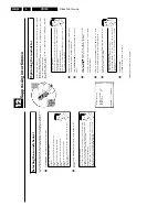
Direction for use
GB 39
VR120
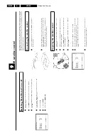
3.
Switch
off
the
clock
display
To
save
energy,
you
can
switch
off
the
clock
display
on
the
video
recorder.
Programmed
(TIMER)
recordings
will
still
take
place.
1
Switch
on
the
TV
set.
If
required,
select
the
programme
number
for
the
video
recorder.
2
Press
MENU
on
the
remote
control.
The
main
menu
will
appear.
3
Select
the
line
'
SPECIAL
SETTINGS
'
with
P
r=
or
;q
P
and
confirm
with
OK
.
SPECIAL
SETTINGS
OSD
è
O
N
p
CLOCK
DISPLAY
OFF
REPEAT
PLAY
OFF
DIRECT
RECORD
ON
________________________________
EXITpMENU
STOREpOK
4
To
switch
off
the
time
display
on
the
video
recorder,
select
in
the
line
'
CLOCK
DISPLAY
'
with
P
'
OFF
'.
How
can
I
switch
on
the
clock
display?
Select
with
Q
'
ON
'
(time
display
switched
on).
5
Confirm
with
OK
.
'
STORED
'
will
briefly
appear
on
the
TV
screen.
6
To
end,
press
MENU
.
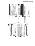
Switching
the
on/screen
display
(OSD)
off
or
on
Along
with
the
on
screen
menu,
the
OSD
(On
Screen
Display)
also
displays
information
on
the
current
operating
status
(counter,
playback,
recording,
TV
channel,
etc.)
on
the
TV
screen.
You
can
switch
off
the
information
about
the
operating
status
so
that
the
on
screen
display
(OSD)
is
not
recorded
when
copying
video
cassettes.
1
Switch
on
the
TV
set.
If
required,
select
the
programme
number
for
the
video
recorder.
2
Press
MENU
on
the
remote
control.
The
main
menu
will
appear.
3
Select
line
'
SPECIAL
SETTINGS
'
using
P
r=
or
;q
P
and
confirm
with
OK
.
SPECIAL
SETTINGS
OSD
è
O
N
p
CLOCK
DISPLAY
OFF
REPEAT
PLAY
OFF
DIRECT
RECORD
ON
________________________________
EXITpMENU
STOREpOK
4
In
the
line
'
OSD
',
select
the
desired
setting
with
P
.
Which
settings
can
I
choose?
'
ON
'
:
Shows
the
OSD
for
a
few
seconds
only.
'
OFF
'
:
Switches
off
the
OSD.
5
Confirm
with
OK
.
6
To
end,
press
MENU
.
Summary of Contents for VR570
Page 12: ...Direction for use GB 12 VR120 3 3 Direction for use RT111 RT116 RT112 RT114 RT123 RT121 RT128 ...
Page 15: ...Direction for use GB 15 VR120 3 SAT VR870L VR870CC VR720 Set width 435 mm ...
Page 56: ...Service modes Repair tips GB 56 VR120 5 Engineer s remarks ...
Page 79: ...Circuit diagrams and PWB layouts Wiring diagram 79 VR120 7 7 16 Wiring Diagram Motherboard ...
Page 81: ...Circuit diagrams and PWB layouts Wiring diagram 81 VR120 7 Engineer s remarks ...
Page 82: ...82 VR120 7 Circuit diagrams and PWB layouts Wiring diagram Engineer s remarks ...
Page 83: ...Circuit diagrams and PWB layouts Wiring diagram 83 VR120 7 7 18 Mother board component side ...
Page 119: ...Tape deck GB 119 VR120 10 ...
Page 123: ...Tape deck GB 123 VR120 10 Engineer s remarks ...


