Direction for use
GB 42
VR120
3.
L
Suppressing
interference
Optimising
the
modulator
In
some
reception
locations
it
is
possible
that
a
T
V
channel
will
be
sent
on
the
same
or
sim
ilar
frequency
as
the
video
recorder.
Result:
As
soon
as
the
video
recorder
is
switched
on,
the
reception
quality
for
this
or
sev
eral
other
TV
channels
will
decreased.
The
following
steps
will
show
you
how
to
change
the
pre-set
'transmission'
(modula
tor)
frequency
on
the
video
recorder.
What
is
a
modulator?
This
electronic
component
in
the
video
recorder
allows
the
device
to
transmit
audio
and
video
signals
via
the
aerial
cable.
These
signals
can
be
received
TV
set
just
like
TV
channels.
What
is
an
modulator
frequency?
This
frequency
or
channel
indicates
the
frequency
or
channel
on
which
the
audio
or
video
signal
is
transmitted.
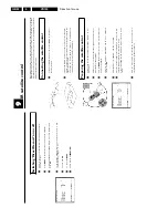
1
Switch
on
the
TV
set.
Select
the
programme
number
used
for
video
recorder
playback
(see
TV
operating
instructions).
2
Press
STOP/EJECT
?
to
eject
any
cassette
that
might
be
in
the
device.
3
Press
the
STOP
h
button
on
the
remote
control.
Then
press
STOP/EJECT
?
until,
e.g.
'
M591
'
appears
in
the
display.
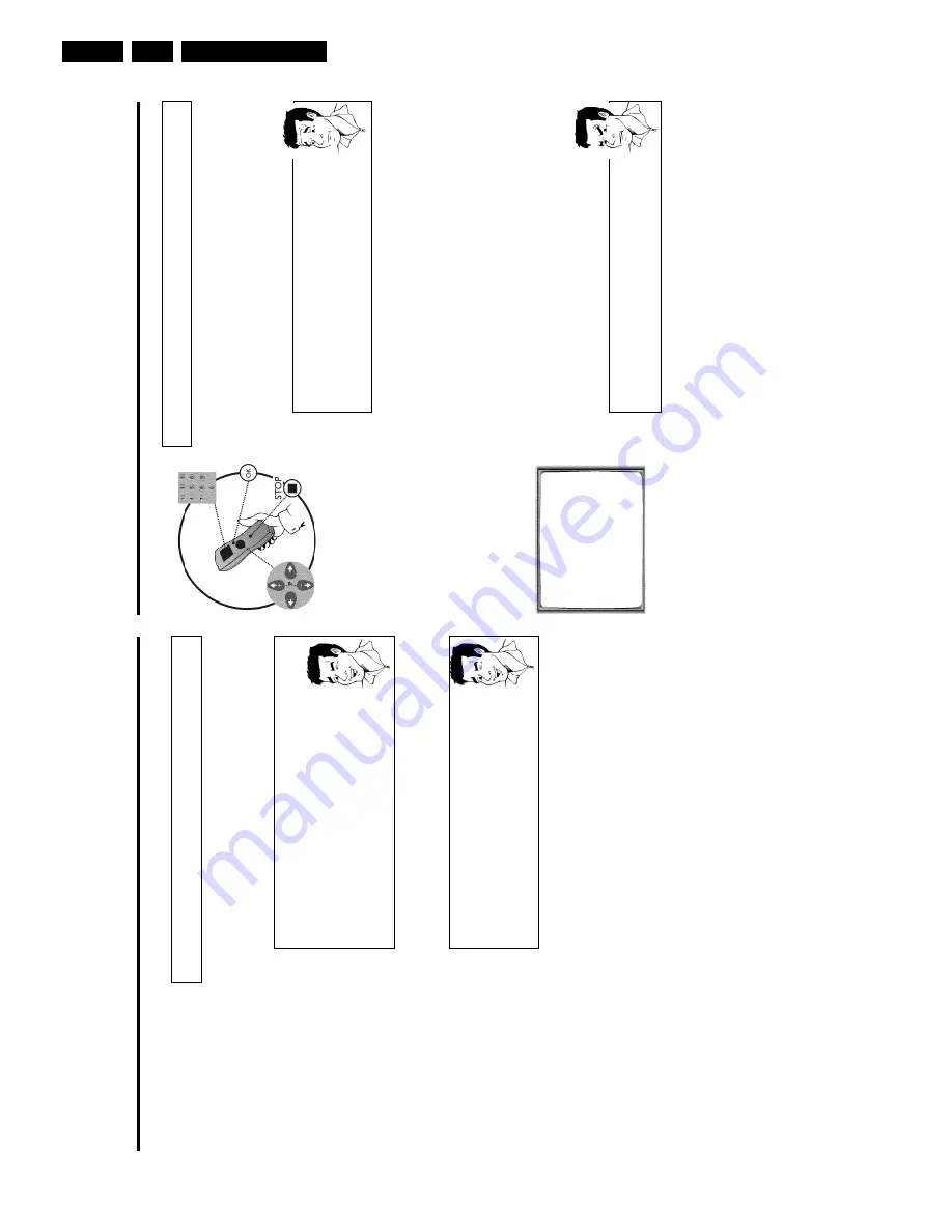
The
video
recorder
will
now
transmit
a
test
image
on
UHF
channel
36/Frequency
591MHz.
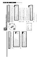
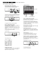
OPTIMIZE
MODULATOR
OPTIMIZE
FREQUENCY
591
p
MODULATOR
ON
SOUND
SYSTEM
G
________________________________
EXITpMENU
STOREpOK
4
Select
line
'
OPTIMIZE
FREQUENCY
'
using
;q
P
or
P
r=
.
Enter
the
new
modulator
frequency
with
the
number
buttons
0-9
.
5
Tune
in
the
TV
set
to
the
new
modulator
frequency
(channel
21
-
69)
shown
in
the
video
recorder
display.
a
Sound
interference
occurs
b
The
wrong
sound
system
could
have
been
selected.
In
line
'
SOUND
SYSTEM
',
select
the
TV
system
with
the
least
sound
disruptions
using
P
or
Q
.'
G
'
(TV
system
PAL-B,G)
or
'
K
'
(TV
system
SECAM-D,K).
6
Confirm
with
OK
.
'
STORED
'
will
appear
briefly
on
the
screen.
Optimising
the
modulator
is
now
complete.
Selecting
the
sound
channel
You
can
select
the
desired
sound
channel
during
playback
or
while
receiving
TV
channels
via
the
video
recorder.
This
allows
you
to
select
a
desired
language
for
multi-language
transmissions.
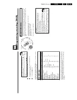
1
Press
SELECT
.
This
will
show
the
current
sound
setting.
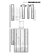
What
goes
on
behind
the
settings?
'
STEREO
':
Left
and
right
stereo
(HIFI)
sound
tracks
can
be
heard.
'
LEFT
':
The
left
stereo
(HIFI)
sound
track
can
be
heard.
'
RIGHT
':
The
right
stereo
(HIFI)
sound
track
can
be
heard.
'
MONO
':
The
mono
(linear)
sound
track
can
be
heard.
'
MIXED
':
The
mono
(linear)
sound
track
can
be
heard
at
the
same
time
as
the
stereo
(HIFI)
sound
tracks.
2
Keep
pressing
SELECT
until
the
desired
setting
appears
in
the
display.
Automatic
switch
to
'
MONO
'
If
a
T
V
channel
does
not
transmit
a
stereo
signal
or
if
there
is
no
stereo
signal
recorded
on
the
video
cassette,
the
video
recorder
will
automatically
switch
to
'
MONO
'.
You
will
not
be
able
to
select
any
other
settings.
Playing
back
an
audio
dubbing
When
dubbing
video
recordings,
the
mono
(linear)
sound
track
is
recorded
with
a
new
sound
signal.
The
stereo
(HIFI)
sound
track
is
kept.
To
hear
the
dubbed
section,
you
must
select
either
'
MONO
'o
r'
MIXED
'.
Summary of Contents for VR570
Page 12: ...Direction for use GB 12 VR120 3 3 Direction for use RT111 RT116 RT112 RT114 RT123 RT121 RT128 ...
Page 15: ...Direction for use GB 15 VR120 3 SAT VR870L VR870CC VR720 Set width 435 mm ...
Page 56: ...Service modes Repair tips GB 56 VR120 5 Engineer s remarks ...
Page 79: ...Circuit diagrams and PWB layouts Wiring diagram 79 VR120 7 7 16 Wiring Diagram Motherboard ...
Page 81: ...Circuit diagrams and PWB layouts Wiring diagram 81 VR120 7 Engineer s remarks ...
Page 82: ...82 VR120 7 Circuit diagrams and PWB layouts Wiring diagram Engineer s remarks ...
Page 83: ...Circuit diagrams and PWB layouts Wiring diagram 83 VR120 7 7 18 Mother board component side ...
Page 119: ...Tape deck GB 119 VR120 10 ...
Page 123: ...Tape deck GB 123 VR120 10 Engineer s remarks ...


