Service modes, Repair tips
GB 51
VR120
5.
Error table:
The 3 digits on the right represent the deck error condition:
(e.g.: 053 = during Play )
The error code can be reset in this step with the CLEAR key.
Functiontable:
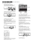
Step 03: Deck sensors and manual tracking
By pressing the SELECT key whilst step 03 is flashing, the
deck sensors will be displayed in one digit as either 1 or 0.
In the service test program, the tracking is always in the
centre position.
Only in this step can the value for the required tape running
setting be changed, manually in the PLAY function with the
UP / DOWN keys. After leaving the mode with the SELECT
key, the tracking value always resets itself to the centre
position and cannot be changed.
Step 04: Display of the operating hours counter:
By pressing the SELECT key whilst step 04 is flashing, the
operating hours counter shows how many hours the head
disk has turned. The hours are displayed as a 4-digit decimal
number.
Step 05: Display of the IIC - Bus Communication:
By pressing the SELECT key whilst step 05 is flashing, the
available IIC- components will be displayed with symbols.
The following errors are visible in the display when the start
up routine of the set isn’t working properly.
h n D C
are used to display the deck status
START
init switch (INIT)
END
record protection (RECP)
DEC
Loading pulses (FTA)
0
no error
1
threading error
2
no capstan pulses
3
tape broken
4
no pulses left reel
5
no pulses right reel
6
head motor error
012 Standby
114
VISS write
211/491 Slowmotion 1/24
014 Autotracking
115
Viss erase
212/492 " " 1/14
031 Play-3
125
Tuner - Stopout
215/495 " " 1/7
034 Slow_reverse
126
Auto Remain Funct.
216/496 " " 1/2
041 Still Picture
130/410 ATTS Function
217/497 " " -1/24
042 Fast
168/448 Frame+
218/498 " " -1/14
044 Play-9
169/449 Frame-
219/499 " " -1/7
045 Eject
170/450 Play-11
220/500 " " -1/2
046 Play9
171/451 Play-7
222/502 Edit Record
047 Play-1
172/452 Play-5
223/503 Align of Gap
048 Pause
173/453 Play5
238/518 Pause
050 Rewind
174/454 Play7
239/519 SPC align
052 Wind
175/455 Play11
246/526 Edit Pause
053 Play
196/456 Tuner - Eject
247/527 Slow motion 1/10
054 Stop out
197/457 Standby Eject
248/528 " " 1/18
055 Record
199/459 Audio Dubbing
249/529 " " -1/10
112 Index next
202/482 Audio Dubb. Pause
250/530 " " -1/18
113 Index previous
206/486 Reset Tapecounter
253/533 Key Released
E000
IIC-Data line is low
E001
IIC-Clock line is low
E002
EEPROM give no acknowledgement
Symbol Description
Component
Position
v
VPS or VPO IC
SDA5650 or SDA5652
7502
DEC
FM ST / NIC IC
MSP 3415D
7761
x
FM St IC
TDA 9873
7760
W
Video switch IC
STV 6401
7904
D
FM Audio IC
TDA 9605H
7650
k
Tuner Philips
TP9xx
1701
o
Tuner Alps
TMRxx/TCBZ4
1701
u
Modulator Phil
TP9xx
1701
LP
Modulator Alps
TMRxx/TCBZ4
1701
8
Signal electr. IC
LA71595M
7004
Summary of Contents for VR570
Page 12: ...Direction for use GB 12 VR120 3 3 Direction for use RT111 RT116 RT112 RT114 RT123 RT121 RT128 ...
Page 15: ...Direction for use GB 15 VR120 3 SAT VR870L VR870CC VR720 Set width 435 mm ...
Page 56: ...Service modes Repair tips GB 56 VR120 5 Engineer s remarks ...
Page 79: ...Circuit diagrams and PWB layouts Wiring diagram 79 VR120 7 7 16 Wiring Diagram Motherboard ...
Page 81: ...Circuit diagrams and PWB layouts Wiring diagram 81 VR120 7 Engineer s remarks ...
Page 82: ...82 VR120 7 Circuit diagrams and PWB layouts Wiring diagram Engineer s remarks ...
Page 83: ...Circuit diagrams and PWB layouts Wiring diagram 83 VR120 7 7 18 Mother board component side ...
Page 119: ...Tape deck GB 119 VR120 10 ...
Page 123: ...Tape deck GB 123 VR120 10 Engineer s remarks ...


