background image

 84

VR120

7.

Circuit diagrams and PWB layouts, Wiring diagram

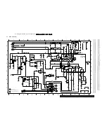
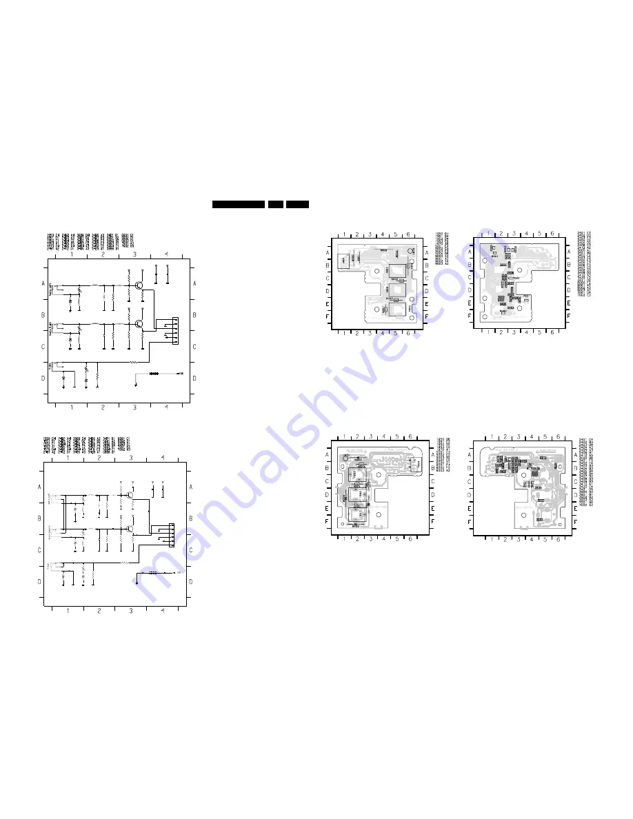
7.19 Connector print (ACP10)

7.20 Connector print (ACP1)

V

V

V

GNDESD

GNDV

6001

BZX284-C12

+12V

16

1u

2403

GNDA

470K

3407

1

2

3

3404

470K

1u

16

1952

3403

1M

2405

2406

100n

GNDA

GNDESD

100n

2402

GNDA

GNDA

GNDA

GNDA

1970

1

GNDA

100U

5004

2

3

GNDV

BC847C

7001

1953

1

GNDA

150R

3410

3421

+12V

BZX284-C12

6000

+12V

220u

5002

6003

BZX284-C12

3

GNDV

GNDA

1951

1

2

470p

2401

GNDA

220u

5001

3420

3406

4K7

75R

3401

GNDESD

+12V

BZX284-C12

6002

1950

1

2

3

4

5

6

BLM21

GNDA

7002
BC847C

3000

680K

4K7

3409

+12V

3405

+12V

680K

3408

GNDESD

5003

100U

+12V

2404

470p

GNDA

2412

GNDESD

3402

1M

GNDA

GNDV

GNDA

AUDIO_L

+12V

VIDEO

AUDIO_R

to AMB
1955

to AMB
1955

V

V

V

3421

GNDA

GNDA

I001

3404

470K

3405

680K

I008

GNDESD

GNDA

1M

3402

2404

470P

1950

1

2

3

4

5

6

GNDESD

GNDA

1970

1

HLEM

7002
BC847C

2412

470K

3407

1952

Cinch

1

2

3

6003

BZX79-C12

I014

GNDV

I007

I017

I019

100n

2402

I015

GNDA

GNDA

I013

3406

4K7

220u

5002

3401

3420

BZX79-C12

6002

75R

BLM21

I006

I016

3000

GNDA

GNDA

GNDESD

+12V

GNDA

680K

3408

220u

5001

5003

100U

+12V

+12V

I004

3410

I005

I002

150R

GNDA

I003

470P

2401

BZX79-C12

6000

1953

Cinch

1

2

3

+12V

1951

Cinch

1

2

3

GNDV

GNDESD

3403

1M

GNDV

GNDESD

2405

1u

16

I009

4K7

3409

GNDA

I010

GNDA

GNDA

100U

5004

BC847C

7001

2406

100n

I018

6001

BZX79-C12

+12V

16

1u

2403

+12V

I012

+12V

I011

GNDV

GNDA

AUDIO_L

+12V

VIDEO

AUDIO_R

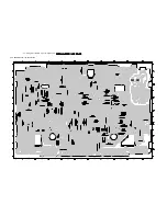
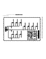
7.21 Connector print lay out (ACP10)

7.22 Connector print lay out (ACP1)

6

ACP10

c

e

b

c

e

b

6

1

ACP10

Summary of Contents for VR570

Page 1: ...ions for use 12 4 Dismantling instructions 46 5 Service modes Repair tips 49 6 Block diagrams Waveforms Wiring diagram 57 7 Circuit diagrams and PWB layouts 64 8 Electrical alignments 91 9 Circuit descriptions and List of abbreviations 97 10 Tape deck 113 11 Exploded views 124 12 Spare parts list 128 Survey of versions Survey of remote controls 02 03 PAL B G VPS PDC 05 PAL I UK 07 PAL I Ireland 11...

Page 2: ... SEC 74 Video Signal Processing VS 75 VPS PDC OSD Part VPO 76 In Out Part IO 77 FOLLOW ME Part FOME 78 Wiring Diagram 79 Mother board solder side 80 Mother board component side 83 Connector print ACP10 84 Connector print ACP1 84 Connector print QBOE1 85 Connector print QBOG1 85 Connector print ACP35 86 Key print AKP35 87 Illumination print AKP13 88 Key print AKP36 89 Shuttle board ASP10 89 Shuttle...

Page 3: ...W 58 á á á á á á á á á VR402 58 á á á á á á á á á VR420 02 á á á á á á VR420 39 á á á á á á á á á á á VR420 58 á á á á á á á á á VR520 02 á á á á á VR520 07 á á á á á VR520 16 á á á á á VR520 58 á á á á á á á á á VR570 02 á á á á á á VR570 07 á á á á á á VR570 16 á á á á á á VR570 39 á á á á á á á á á á á VR570 58 á á á á á á á á á VR572 02 á á á á á á VR572 16 á á á á á á VR620 02 á á á á á á VR6...

Page 4: ... á á á á á VR870L 02 á á á á á á á VR870L 07 á á á á á á á VR870L 16 á á á á á á á VR870L 39 á á á á á á á á á á á á VR870L 58 á á á á á á á á á á SB140 03 á á á á á SB140 38 á á á á á á á á á á SB145 03 á á á á á á SB145 11 á á á á á á SB445 11 á á á á á á SB445 38 á á á á á á á á á á á SB645 03 á á á á á á SB645 11 á á á á á á SB645 38 á á á á á á á á á á á SB745 03 á á á á á á SB745 11 á á á á ...

Page 5: ...á á á á Tape Counter Time Left h m á á á á á á á á á VISS next prev index blank tape search á á á á á á á á á á á á á á á á á á á á á Features Plug Play á á á á á á á á á On Screen Display OSD á á á á á á á á á Welcome Screen á á á á á á á á á Auto Install Search Store Tuning á á á á á á á á á á á á á á á á á á á á á Easy link NexTView Link P50 Follow TV analog á á á á á á á á á Direct Record á á ...

Page 6: ... á á á á á á á á á á á á á á á á á á On Screen Display OSD á á á á á á á á á á á á á á á á á á á á Welcome Screen á á á á á á á á á á á á á á á á á á á á Auto Install Search Store Tuning á á á á á á á á á á á á á á á á á á á á Easy link NexTView Link P50 Follow TV analog á á á á á á á á á á á á á á á á Direct Record á á á á á á á á á á á á á á á á 16 9 pin 8 á á á á á á á á á á á á á á á á Digital...

Page 7: ... á á á á á á á á á On Screen Display OSD á á á á á á á á á á á á á á á á á á á á Welcome Screen á á á á á á á á á á á á á á á á á á á á Auto Install Search Store Tuning á á á á á á á á á á á á á á á á á á á á Easy link NexTView Link P50 á á á Follow TV analog á á á á á á á á á á Direct Record á á á á á á á á á á 16 9 pin 8 á á á á á á á á á á á á á á á á á á á á Digital Studio Picture Control á á ...

Page 8: ...ures Plug Play á á á á á á á á á á á á á á á á á á á On Screen Display OSD á á á á á á á á á á á á á á á á á á á Welcome Screen á á á á á á á á á á á á á á á á á á á Auto Install Search Store Tuning á á á á á á á á á á á á á á á á á á á á á á easy link NexTView Link P50 á á á á á á á Follow TV analog á á á á á á á á á á á á á á á á á á á Direct Record á á á á á á á á á á á á á á á á á á á 16 9 pin...

Page 9: ... Ohm passive loop through from AV2 Euroconnector AV2 SCART plug 2 Connection to decoder SAT tuner video disc 2nd VCR Pin 1 ARO audio right out 500 mVrms 3 dB Rout 1 kOhm Pin 2 ARI audio right in 0 2 Vrms to 2Vrms Rin 10 kOhm Pin 3 ALO audio left out 500 mVrms 3 dB Rout 1 kOhm Pin 6 ALI audio left in 0 2 Vrms to 2 Vrms Rin 10 kOhm Pin 7 Blue out Pin 8 Switching input only low 2 V low Rin 10 kOhm hi...

Page 10: ...ys be connected to the mains via a suitable isolating transformer Never replace any modules or any other parts while the set is switched on Use plastic instead of metal alignment tools This in order to prelude short circuit or to prevent a specific circuit from being rendered unstable 2 1 1 Remarks The direct voltages and oscillograms ought to be measured relative to the set mass The direct voltag...

Page 11: ... case of a major change in the set the evolution code is incremented E g AA becomes AB Tape deck Note The production code and the serial number on the tape deck do not correspond to the production code and the serial number on the type plate Printed circuits The sticker is generally located on the copper side of the board Example Note The production code number might not always be mentioned In cas...

Page 12: ...Direction for use GB 12 VR120 3 3 Direction for use RT111 RT116 RT112 RT114 RT123 RT121 RT128 ...

Page 13: ...lect Cursor left P Select Cursor right Pq Select To select a programme number rP Select To select a programme number PLAY G Playback To play a recorded cassette H Rewind During STOP and STANDBY rewind during PLAYBACK reverse scanning STOP h Pause Stop To stop the tape except while a TIMER recording is being made I Forward wind During STOP and STANDBY forward wind during PLAYBACK forward scanning I...

Page 14: ...Direction for use GB 14 VR120 3 VR120 VR402 VR520 VR170 VR570 VR572 VR220 VR420 VR270B VR270W VR670B VR670W VR620 VR622 VR627 SB140 SB145 SB445 SB645 SB745 20DV30 45DV30 65DV30 Set width 380 mm ...

Page 15: ...Direction for use GB 15 VR120 3 SAT VR870L VR870CC VR720 Set width 435 mm ...

Page 16: ...k quality For old and often used video cassettes this system reduces interference For new or high quality cassettes it emphasises the details This function allows you to save the playback settings that suit you best Select your own personal settings for this type of film you are currently watching When you connect your video recorder to your television and plug it into the wall socket you will be ...

Page 17: ... scart cable Connecting without a scart cable If you do not wish to use a scart cable The symbols on your video recorder display These symbols can light up on your video recorder display This is where the current operating mode is shown as a symbol LP When you have switched on the LP Long Play function or when you play a tape that has been recorded in LP Long Play When you have switched on the chi...

Page 18: ...ty of the television picture during cassette playback prevention of waves or streaks special programme numbers have been set aside on the TV for the use of video recorders This is usually the highest possible programme number e g 12 16 99 or even programme number 0 For more information please see your TV s operating instructions Connecting with a scart cable Have the following cables ready an aeri...

Page 19: ...est possible number of TV channels It is possible that the TV channels in your country are broadcast in a higher frequency range As soon as this range is reached during the search the video recorder will find the TV channels CLOCK YEAR è 2001 p MONTH 01 DATE 01 TIME 20 00 SMART CLOCK ON ________________________________ EXITpMENU STOREpOK 5 When the automatic TV channel search is complete STORED wi...

Page 20: ...me number that you want to use for the TV channel e g P01 6 In line S CHANNEL select the desired display using P 7 Select the next line with qP or P r 8 Check if the displayed settings for MONTH DATE and TIME are correct 9 When all information is correct save by pressing OK STORED will briefly flash in the video recorder display The initial installation is now complete Satellite receiver If you ar...

Page 21: ... the OK button TV01 will appear in the video recorder display TV01 5 Select programme number 1 on the TV set What is hidden behind the settings NO Display Entry of channels YES Display Entry of special channels What is a special channel TV channels are transmitted in certain pre defined frequency ranges These ranges are divided into channels A specific frequency channel is assigned to each TV stat...

Page 22: ...tween the TV picture and video recorder picture with MONITOR But this only works when you use a scart cable to connect the video recorder to your TV set and your TV set responds to this switch over a I cannot switch my TV set to programme number 1 b If you have connected additional devices to socket EXT 2 AV 2 please disconnect these devices Because of other connected devices the TV set could swit...

Page 23: ... MENU Sorting and clearing TV channels manually After you have performed the automatic channel search you may not agree with the sequence in which the individual TV channels have been allocated to the programme positions programme numbers of the video recorder You can use this function to individually sort the TV channels already saved or to delete unwanted TV channels or those with poor reception...

Page 24: ...ctly Navigation in the screen menu You can check change many functions and settings of your video recorder via the screen menu The individual functions are selected as follows MENU CLOCK AUTO TUNING MANUAL SEARCH FOLLOW TV TV CHANNEL ALLOC RECORD SPEED AUTO STANDBY VIDEOSYSTEM LANGUAGE SPECIAL SETTINGS ________________________________ EXITpMENU OK HOTLINEpCL Call up the menu with MENU To select wi...

Page 25: ...ough step 7 8 To end press TAPE LIST E Tape List General information The Tape List is an integrated database in the video recorder that remembers all recordings made by this video recorder The Tape List helps you keep track of which film is on which cassette The Tape List also gives you quick and easy access to recordings And If desired the video recorder will rewind to the beginning of the select...

Page 26: ...utomatic TV system will switch over automatically If picture sound interference occurs attempt to fix the problem by manually switching the TV system In that case turn to chapter Additional functions section Switching the video color system 3 To stop the playback press STOP h on the remote control or STOP EJECT on the video recorder 4 To eject the cassette press STOP EJECT on the video recorder wh...

Page 27: ...s for slow motion 5 To continue playback press PLAY G Automatic switch off of special functions Many functions e g pause still picture search switch themselves off automatically after a short time in order to protect the cassette and to save energy Do I need to change the playback speed when playing back LP recordings For playback the correct recording speed SP will automatically be selected For m...

Page 28: ...icture setting 2 If the SMART button is not been pressed after a few seconds the selected picture setting will be saved 3 These picture settings will not change until you eject the cassette Searching for tape position without picture forward wind and rewind 1 Stop the tape with STOP h 0 30 21 2 Press H reverse or I forward This will for example appear in the display 3 To stop at a certain place on...

Page 29: ...XT 2 AV 2 Programme number E3 This programme number is used for recording from the audio and video front sockets BBC1 3 To start recording press RECORD OTR n on the remote control or RECORD n on the video recorder This will for example appear in the display Displaying tape position Using OK you can show the tape position in the display G Eliminating picture interference Optimising tracking This vi...

Page 30: ...irst class picture quality LP LongPlay half recording speed double recording time 8 hours can be recorded on a 4 hour cassette E240 with a somewhat reduced picture quality AUTO AUTOmatic Long Play If there is not enough space on the tape to record a programmed recording in standard speed the recording will automatically be made in LP Longplay Otherwise the recording speed will be SP Standardplay 4...

Page 31: ...d not be found in the video recorder s memory Check that all TV channels saved on the TV set are available in the video recorder If required save any missing channels Please read the section Manual TV channel search 3 Stop recording with STOP h 5 Confirm with OK 6 To end press MENU Automatic controlled recording from a satellite receiver RECORD LINK This function automatically starts recording on ...

Page 32: ...3 Press the MENU button on the video recorder remote control The main menu is displayed 4 Select the line SPECIAL SETTINGS with P r or qP and confirm with OK SPECIAL SETTINGS OSD è ON p CLOCK DISPLAY OFF REPEAT PLAY OFF DIRECT RECORD ON ________________________________ EXITpMENU STOREpOK 5 Select line SAT IR CODE NR with P r or qP 6 Enter the IR code number that corresponds to your Set Top Box usi...

Page 33: ...parate recordings a My Set Top Box does not switch to programme number 12 b Please check that you entered the correct code number Repeat step 6 b Also try other code numbers b Please make sure that the IR electronic eye on the Set Top Box is not blocked b You may wish to reposition the SAT mouse repeat steps 1 and 6 8 Confirm the correct code number with OK 9 Affix the satellite control to the Set...

Page 34: ...tected Using Tape List To save a recording in the Tape List or to use a Tape List cassette enter the cassette number using the number buttons 0 9 on the remote control The cassette is being checked You can find more information on the Tape List in the chapter Tape List 8 Switch off with STANDBY ON m The programmed recording will only function when the video recorder is switched off with STANDBY ON...

Page 35: ... with OK The programming information is stored in a TIMER block 6 Insert a cassette with an intact security tab unprotected Problems and solutions for programmed recordings PROBLEM SOLUTION The video recorder will not operate b While a programmed recording is being made you cannot operate your video recorder manually If you want to cancel the programmed recording press STANDBY ON m SWITCH TO STAND...

Page 36: ...enter the cassette number using the number buttons 0 9 on the remote control The cassette is being checked You can find more information on the Tape List in the chapter Tape List 7 Switch off with STANDBY ON m The programmed recording will only function when the video recorder is switched off with STANDBY ON m If any of the TIMER blocks are in use k will light up on the video recorder display Prob...

Page 37: ...ogrammed recordings PROBLEM SOLUTION The video recorder does not react b While a programmed recording is being made you cannot operate your video recorder manually If you want to cancel the programmed recording press STANDBY ON m k will flash in the video recorder display b The video recorder was switched on several minutes before the start of a programmed recording Switch off the video recorder w...

Page 38: ... You can switch off the automatic TV system switch over as follows Video colour systems Other countries other video colour systems In central Europe transmissions are broadcast in the PAL system Phase Alternation Line standard France uses SECAM Séquentiel à mémoire In some countries USA and Japan TV viewers receive their programmes as an NTSC signal National Television System Committee 1 Press MEN...

Page 39: ...l briefly appear on the TV screen 6 To end press MENU Switching the on screen display OSD off or on Along with the on screen menu the OSD On Screen Display also displays information on the current operating status counter playback recording TV channel etc on the TV screen You can switch off the information about the operating status so that the on screen display OSD is not recorded when copying vi...

Page 40: ...ss MENU on the remote control The main menu will appear MENU CLOCK AUTO TUNING MANUAL SEARCH FOLLOW TV TV CHANNEL ALLOC RECORD SPEED AUTO STANDBY VIDEOSYSTEM LANGUAGE SPECIAL SETTINGS ________________________________ EXITpMENU OK HOTLINEpCL 3 Press the SELECT button on the remote control In addition press the number button 2 to change the remote control to VCR2 4 Confirm with OK The main menu will...

Page 41: ...eact to the selected code numbers If this is the case you unfortunately cannot use this function By using the TV buttons on the panel in the middle of the control you can qS increase the TV volume Sr decrease the TV volume qTV next programme number TV r previous programme number To switch off the TV TV m press Sr and TV r at the same time Automatic switch off If you haven t used the video recorder...

Page 42: ...h the number buttons 0 9 5 Tune in the TV set to the new modulator frequency channel 21 69 shown in the video recorder display a Sound interference occurs b The wrong sound system could have been selected In line SOUND SYSTEM select the TV system with the least sound disruptions using P or Q G TV system PAL B G or K TV system SECAM D K 6 Confirm with OK STORED will appear briefly on the screen Opt...

Page 43: ... power supply 2 Press and hold the STANDBY ON m button on the device and reconnect to the mains power supply 3 Release the button when OSD appears in the video recorder display Cassette is jammed in the video recorder b Don t use force Pull out the mains plug for a moment Remote control does not work b Remote control not pointed toward the video recorder point it at the video recorder b There is a...

Page 44: ...ion please see the section Preventing accidental erasing of cassettes in chapter Manual Recording b VPS PDC switched on but VPS PDCtime wrong enter VPS PDCtime exactly to the minute Have your aerial checked Programmed recording does not work b You have programmed the wrong time or date check time and date b Check time and date If time and date are wrong despite manual setting you can switch SMART ...

Page 45: ...c 32 13 20 02 15 36 41 Magnadyne 12 23 Magnafon 12 Manesth 30 20 25 Marantz 01 Matsui 02 39 18 20 04 06 07 10 28 Memorex 02 Metz 34 Mitsubishi 07 14 16 Mivar 27 Multitech 02 12 Neckermann 01 Nikkai 06 21 05 10 25 Nobliko 12 Nokia 41 33 Nordmende 15 Oceanic 33 Orion 28 30 31 39 Osaki 05 10 20 21 25 Oso 21 Osume 05 10 Otake 29 Otto Versand 03 07 20 30 01 Palladium 35 38 Panama 20 25 Panasonic 24 34 ...

Page 46: ...r screws A Push catch S inwards lifting lid at the same time to move out of groove Slide housing cover back by approx 1 cm Push centre of housing cover sides on underside approx 1 cm outwards and lift up the housing cover Assembly Assemble in reverse order 2 Base plate Figure 4 2 The base plate may not be removed from the frame 3 Front panel Figure 4 2 Preparation Dismantle the housing lid as desc...

Page 47: ...t has to be released for a second time The frame can be removed by lifting it off Turn the motherboard drive unit and move it into the service position Figure 4 6 if necessary The device is operational in this position Eject must NOT be used Caution Adjustments can not be made in the service position Eject must NOT be used Assembly Position the frame with the top open onto a level surface Hold the...

Page 48: ... through the hole in the back panel Remove the cables from the drive Bend back the guard of the scanner cable Remove the scanner cable from the socket Return the lift into the Eject position Slightly lift the left rear side of the drive to undo the connector to the capstan motor Press both catches S together with fine pliers and lift the drive around the snapholders The drive may be separated from...

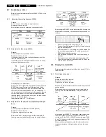
Page 49: ...sition set before entering the service test program is maintained 5 2 2 Activating the service test program Press and hold down the STOP key on the remote control Then press the PLAY key on the recorder and keep it depressed for at least 5 sec The STOP key on the remote control may be released whilst the PLAY key on the recorder is pressed The service test program can be selected in any operating ...

Page 50: ... is shown on the display Checking the drive function Loading and unloading time The signal FTA of the photoelectric barrier which controls the revolutions of the loading motor is used as a reference for the loading and unloading time Stopping of supply or take up reels The tacho signals of the left WTL and right WTR winding disks are used as control reference Stopping of head drum motor This is mo...

Page 51: ...ch INIT END record protection RECP DEC Loading pulses FTA 0 no error 1 threading error 2 no capstan pulses 3 tape broken 4 no pulses left reel 5 no pulses right reel 6 head motor error 012 Standby 114 VISS write 211 491 Slowmotion 1 24 014 Autotracking 115 Viss erase 212 492 1 14 031 Play 3 125 Tuner Stopout 215 495 1 7 034 Slow_reverse 126 Auto Remain Funct 216 496 1 2 041 Still Picture 130 410 A...

Page 52: ...ing the UP and DOWN keys the available options A to G can be selected The display shows the last stored value in decimal format In case of an invalid entry value 255 the activation of the OK key causes the content of the last stored option to be displayed and OK does not appear in the display Depending on the model some bits are software or default protected and cannot be changed by an entry In th...

Page 53: ...break the copper foil on the printed circuit board Figure 5 1 3 Installation of leadless components a Presolder the contact points on the circuit board b Using tweezers press down the part and solder both electrodes as shown below Note Do not glue the replacement component to the circuit board 5 3 2 How to remove install the Flat Pack IC How to remove the Flat Pack IC Using a hot air Flat Pack IC ...

Page 54: ...eld by glue or the P C B may be damaged if force is used If the IC is glued heat the IC with hot air to loosen the glue Using a special removal device a Apply extra tin lead solder onto the pins b Heat the IC to melt the glue which has been used to affix it c Use a solder removing device with a special punch which matches the contours of the IC to remove the IC At the other corners there are print...

Page 55: ...ner voltage of Zener diodes is indicated as such on schematic diagrams Example BZX79C20 Zener voltage 20 Volts 5 8 How to identify connectors on schematic diagrams Each connector is labeled with a connector number and a pin number indicating to what component it is connected in other words its counterpart Use the Connecting Wiring Diagram to find the connections between associated connectors Examp...

Page 56: ...Service modes Repair tips GB 56 VR120 5 Engineer s remarks ...

Page 57: ...Waveforms 6 1 Block diagram Video TDA9817 TDA9818 SDA 5650 SDA 5652 Interconnections AF page 73 VPO page 76 VS page 75 VS_S page 74 AL page 72 AIO1 page 66 AIO2 page 65 DE page 67 FM ST page 70 FM NIC page 71 FV page 69 FOME page 78 I O page 77 PS page 64 ...

Page 58: ... 2 Block diagram Audio Mono ADJ Interconnections AF page 73 VPO page 76 VS page 75 VS_S page 74 AL page 72 AIO1 page 66 AIO2 page 65 DE page 67 FM ST page 70 FM NIC page 71 FV page 69 FOME page 78 I O page 77 PS page 64 Engineer s remarks ...

Page 59: ...9 VR120 6 6 3 Block diagram Audio Stereo Interconnections AF page 73 VPO page 76 VS page 75 VS_S page 74 AL page 72 AIO1 page 66 AIO2 page 65 DE page 67 FM ST page 70 FM NIC page 71 FV page 69 FOME page 78 I O page 77 PS page 64 ...

Page 60: ...60 VR120 6 Block diagrams Waveforms 6 4 Supply voltages and Bus diagram 1941 SAT MOUSE o M63100BFP ...

Page 61: ...5 Supply voltages and Bus diagram Interconnections AF page 73 VPO page 76 VS page 75 VS_S page 74 AL page 72 AIO1 page 66 AIO2 page 65 DE page 67 FM ST page 70 FM NIC page 71 FV page 69 FOME page 78 I O page 77 PS page 64 Engineer s remarks ...

Page 62: ... Control AIO1 AIO2 OPTION AC3P1 xU AC3P7 xU AC3B1 xU not used for M63100BFP Interconnections AF page 73 VPO page 76 VS page 75 VS_S page 74 AL page 72 AIO1 page 66 AIO2 page 65 DE page 67 FM ST page 70 FM NIC page 71 FV page 69 FOME page 78 I O page 77 PS page 64 ...

Page 63: ...v 10ms Div 0V TP 9802 SYNC 46 REC A DC 500mV Div 10ms Div 0V TP9803 HP1 47 REC A DC 2 V Div 10us Div 0V IC 7899 B PIN35 DRUM_DIG 49 REC A DC 1 V Div 200us Div 0V IC 7463 PIN11 DRUM 50 REC A AC 5 V Div 2ms Div 0V CON 1948 PIN 1 3 51 REC A DC 200mV Div 10ms Div 0V CON 1948 PIN 5 PG 52 REC A DC 2 V Div 1ms Div 0V IC 7463 PIN6 PG FG 53 REC A DC 2 V Div 20ms Div 0V T 7466 COLLECTOR FTA 54 LOAD A DC 1 V...

Page 64: ...306 B11 9007 I1 9301 G14 3351 F12 3352 F12 3 2307 D10 4303 A14 4305 E13 5009 E8 4 5 G H I 6 7 A B Mains plug HOT CIRCUIT BE CAREFUL AND USE AN 8 5V 15 C 13 6V 10 7V 10 6V 1306 G12 2300 A10 2301 C11 6312 H6 6313 H7 3309 C7 3310 C11 C 3314 E6 3315 D8 3316 E10 5 6 7 8 9 10V ZL Type 0040 B5 for 1Watt 3K9 1 and 470R 0V H B E F 3 OSCILLOGRAMS 3307 C10 3308 C5 1 A D 1 2 3 3304 SIOV S05K420GAS3 L 0 8V 5 2...

Page 65: ... 3176 1R 47u 73 X1 74 X2 BAT85 6171 14 PF0 S8 15 PF1 S9 16 PF2 S10 17 PF3 S11 18 PF4 S12 19 PF5 S13 79 TEST1 80 TEST2 81 TEST3 30 VKK PC7 G7 28 PD0 G8 29PD1 G9 6 PE0 S0 7 PE1 S1 8 PE2 S2 9 PE3 S3 10 PE4 S4 11 PE5 S5 12 PE6 S6 13 PE7 S7 76 75 ITEST 77 PB0 XT1 78 PB1 XT2 20 PC0 G0 21 PC1 G1 22 PC2 G2 23 PC3 G3 24 PC4 G4 25 PC5 G5 26 PC6 G6 27 7899 A TMP93CT76F 64 ADGND 65 ADREF 71 CLK 72 DGND 31 DVC...

Page 66: ...847BW I845 I832 I826 GNDD 2812 33p I827 3848 100R 10R 3805 GND 10K 3879 F802 S298P 7461 22K 3854 I822 3817 470R GNDD GND I839 I828 GND I836 GNDD F828 10n 2808 GNDD 5VD I855 I874 47K 3897 I803 I810 I820 7462 47K 3864 S298P 7803 BC857BW 1K 3796 F8204 I846 F826 5V_1WSTBY I823 3896 4K7 2n2 2805 9802 F8203 3803 2K2 I842 I816 7804 BC337 25 F829 1K 3872 3833 10K GNDD 22K 3888 F809 22K 3887 3828 10K 330R ...

Page 67: ... 3 4 5 6 7 8 F470 100n 2464 GNDDE F4803 5V_1WSTBY 5V_1WSTBY 2478 3470 220R F469 F4605 3486 10K I475 GNDDE I485 390K 3548 GNDS GNDDE GNDS F4601 3489 390R 2492 10u 4K7 3471 F4805 GNDDE 2488 I465 F4606 I477 3460 22K 2467 47n I474 4n7 2486 3484 10K GNDM1 GNDM1 GNDDE 2462 GNDDE 100n 2469 F4703 220u 2n2 2480 5VD C462 F4602 I468 I478 33n 2477 GNDDE GNDDE 3482 33K 42 VCTL 11 20 VP1 21 VP2 VREF2 4 40 W RIN...

Page 68: ... 2714 220p 220p 220p 40 4 trap 2718 22n 22n 22n 22n 22n 22n 22n 22n Deemphasis MONO 2719 22u 22u 22u 22u 22u 22u 22u 22u FM PLL Demodulator 2722 470p 470p 470p 470p 470p 470p 470p 470p 470p sieve Audio Modulator IN 2795 15p Video Trap widen 3710 220E 220E 220E 220E 220E 220E Video Trap Bypass 3711 3k3 3k3 3k3 3k3 3k3 3k3 Video Amplitude Multistdt 3714 100E 100E 100E 40 4 trap 3715 330E 220E 220E 2...

Page 69: ...04 E7 1 8V 3 1 not used 0 14 F706 D5 6 8 0V 13 12 2722 G2 0 3733 D15 3734 E13 2 5V 0V 2707 C9 2709 C10 3 5V 2 5V 3714 D6 1705 D13 5703 C3 not used I739 H6 3 2V 3 2V 3 3V B C 2728 F9 F715 I9 2708 C9 low leakage 0 5V 1707 G10 3V 7KMY 2710 C14 1706 G10 2V 3 3V 2 4V 2723 G3 2 9 5V 2712 G6 2716 G4 2 5V 2 5V 9906 H1 3 1V 2 6V I706 B8 4 33 9V 2715 F9 1 2 7 6 V MEASURED IN RECORD MODE or BGILMONO I712 C10...

Page 70: ...1 E5 2760 E3 2763 E3 4760 C7 2785 D4 2786 D8 4761 D7 2778 A5 5763 C8 2781 A5 9602 E2 9703 E3 I791 I792 2773 3n3 2760 3n3 OUTR 37 P1 42 P2 29 SCL 30 SDA 28 VCC 41 VREF 15 XTAL 3762 5K6 44 36 23 5 9 16 12 11 17 19 20 1 OUTL 43 OUTM 2 3 CDE1 6 CDE2 35 CID 34 CTRIG 27 DGND 40 EXTL 38 EXTM 39 EXTR 25 IFINT 14 LF1 18 LF2 31 LPF 21 MAD 4 22 TDA9873HZ 7760 8 AF1I 10 AF1O 33 AF2I 32 AF2O 13 AFR 7 AGND 24 C...

Page 71: ... 4V D 1 2 D 4768 E8 F 3 4 2792 C2 2793 E7 2 4762 F3 F760 E3 2794 E8 I785 B7 I786 B7 2790 F5 I787 A6 2791 F5 I789 B7 8 7 3765 100R 4767 D8 8 5 2V 1 5V 3 8V 3 8V 4763 F3 I761 F761 18M432 HC 49 U 1761 GNDFMS I783 I782 4762 4763 MCL4148 6761 I787 I785 I788 I774 2792 47p 3p3 I766 100u 5761 2788 5VD 4764 47p 2771 2768 10u GNDFMS 5760 10u 5VA F760 I789 4767 I775 2777 5VD GNDFMS I786 GNDFMS GNDFMS 10u 576...

Page 72: ... BIAS Adj 1V 3 7V 3 8V 12 2V 0 5V 3 7V 3619 C2 3620 D4 3621 C5 0V 0 5V 3 7V I603 A8 Switch F605 A5 F607 A5 3 8V 7608 E2 9412 C1 I629 D2 I630 F7 I631 C2 F601 B5 F603 B6 I642 F9 I645 B5 TD1 OSCILLOGRAMS delete for Stereo 60 I640 F9 I641 C4 V MEASURED IN RECORD MODE 7 6V 3 6V I637 2620 47u 3625 100K GNDEO I600 I610 I636 I620 GNDEO GNDVS GNDEO 75 76 77 78 79 8 80 9 95 96 97 98 99 GNDVS LA71595BM 7004 ...

Page 73: ...4 D2 F667 D1 F662 F7 F671 A4 F672 B5 3653 A5 3654 B8 3655 C9 F652 B8 2654 C1 2663 D8 F664 C8 F665 A5 13 F659 E8 5650 A2 5651 B1 2662 D2 6651 F6 OSCILLOGRAMS V MEASURED IN RECORD MODE 2672 A4 15 2671 F7 I653 E2 I656 D2 I657 D2 9 8 2 6 5 2675 B1 2674 A2 7 6 16 2665 E2 18 2667 E9 17 19 A I670 B6 C B D F657 11 2677 A4 2676 B2 I655 D2 F663 F2 4 6V 2653 C9 F651 C8 2664 E1 F660 D8 F666 A4 2661 D1 3650 39...

Page 74: ...6V 3072 A2 3076 A5 3078 B5 I081 F7 I082 F5 2 1V F088 F4 5 1V 3 2 4V 7 ADJ 5 2V 0 5V 2 7V 2 2V 3V I080 F3 2 8V 2 3V 2 6V 2 7V 0 8V 2 2V 2V 89 F080 B6 I074 A5 2 7V I076 B7 I079 E7 3 9V 1 1V 3 1V 4 4V 2 6V 2 6V I071 2 6V 7072 B2 2 2 6V 0 4V F076 A6 4 3V F078 A8 I090 B8 4 5V 2V F074 I084 12K 3094 7073 BC847BW 15K 3074 I076 I089 I074 I064 5VA 680R 3095 220p 2074 I088 F088 7075 BC847BW I083 F075 F080 10...

Page 75: ...13 I049 F13 F004 B12 I051 I8 I052 I7 F007 D12 F008 H12 F009 G10 F010 G10 I338 G12 I339 E12 I340 D12 I342 C8 I875 F2 I053 H8 I054 E4 I055 I7 I056 I6 I057 C8 I058 D13 0 3V 5V 3 2V 89 1 8V 2 5V 0 3V 2 1V 2 6V F014 G5 F015 G5 F016 F4 0050 D1 F019 I9 1001 C8 1911 B2 1912 B1 2000 A8 2001 A10 2002 A10 2003 A11 1 9V 9 4V 5V 77 78 79 0 2V 0V 2 1V 0V I333 D4 I334 I7 I335 H7 I336 G8 I337 G11 I045 B5 I046 I5 ...

Page 76: ...01 B7 F502 D8 for VPO only F500 B7 6k8 for VPS for VPS only for VPO only 3508 C3 3509 E4 7 5503 E10 8 9 10 1 for VPS only not used 8 I509 C4 4501 D8 2504 B2 for VPO only 3505 C9 2507 D2 2508 D9 3510 D1 3518 E2 2509 E8 2500 B6 for VPO only I519 E10 3504 B9 4503 E4 10u 5501 100R 3505 2K2 3515 I517 1M 3518 2512 2n2 2508 100n 1K 3517 2501 100n 5VA 5V_STBY C501 3504 100R I518 I502 4504 4502 I519 4508 4...

Page 77: ...470p 2919 I917 2918 470p I912 10u 5901 I911 I908 100n 2909 I927 470p 2921 I926 470p 2920 I931 I923 C901 GND 5V_STBY F5103 F5106 GNDAIO GNDVIO I903 I902 3 GNDAIO GNDVIO GNDAIO 1954 B 1 2 14VM1 GNDVIO GNDVIO BC847BW 7910 GNDAIO 14VM1 390R 3942 100n 2912 GNDAIO GNDVIO F5102 F5603 GNDVIO GNDVIO GNDVIO F5116 BC847BW 7912 2924 68p 7VNEG 5V_STBY I936 BZX284 C6V8 6912 7907 BC847BW 22p 2906 14VM1 5V_STBY 5...

Page 78: ...2 D1 2 3 3538 C2 F530 E2 3533 B3 2 A GNDFOME C530 GNDVIO 2K2 3536 180p 2535 3542 33K 5V_1WSTBY 4K7 3534 100K 3531 33K 3543 15K 3533 13 LM339D 7530 A 5 4 2 3 12 LM339D 7530 D 11 10 BC847BW 7532 5V_1WSTBY 7531 BC847BW 10u 2531 I535 I536 I537 33K 3545 4K7 3535 I540 3541 33K 3530 4K7 F530 3539 10M 2536 1u 2534 180p 2n2 2533 5V_1WSTBY 3546 33K LM339D 7530 C 9 8 14 5V_1WSTBY 100n 2530 I539 5V_1WSTBY 10M...

Page 79: ...Circuit diagrams and PWB layouts Wiring diagram 79 VR120 7 7 16 Wiring Diagram Motherboard ...

Page 80: ...80 VR120 7 Circuit diagrams and PWB layouts Wiring diagram 7 17 Mother board solder side 7172 CLOCK ADJUST ...

Page 81: ...Circuit diagrams and PWB layouts Wiring diagram 81 VR120 7 Engineer s remarks ...

Page 82: ...82 VR120 7 Circuit diagrams and PWB layouts Wiring diagram Engineer s remarks ...

Page 83: ...Circuit diagrams and PWB layouts Wiring diagram 83 VR120 7 7 18 Mother board component side ...

Page 84: ...DA GNDV GNDA AUDIO_L 12V VIDEO AUDIO_R to AMB 1955 to AMB 1955 V V V 3421 GNDA GNDA I001 3404 470K 3405 680K I008 GNDESD GNDA 1M 3402 2404 470P 1950 1 2 3 4 5 6 GNDESD GNDA 1970 1 HLEM 7002 BC847C 2412 470K 3407 1952 Cinch 1 2 3 6003 BZX79 C12 I014 GNDV I007 I017 I019 100n 2402 I015 GNDA GNDA I013 3406 4K7 220u 5002 3401 3420 BZX79 C12 6002 75R BLM21 I006 I016 3000 GNDA GNDA GNDESD 12V GNDA 680K 3...

Page 85: ...2401 B 3 1103 C 6 0005 F 5 4 5 1 6 2 3 E D H C B A G F E D H C B A G F 4 5 1 6 2 3 7 24 Connector print QBOE1 7 25 Connector print QBOG1 QBOE1 40672 00 01 20 QBOE1 40672 00 01 20 1106 7001 2403 2401 2410 3402 3405 2411 1107 1108 1103 2402 2404 2405 2406 3403 6002 6003 7002 3408 3903 3409 5005 6000 6001 2412 3401 3404 3406 3407 3410 QBOE1 40672 00 01 20 5003 5004 5002 1106 3901 5001 1107 1108 1103 ...

Page 86: ... F418 E4 I401 A2 6140 D1 6141 B1 6142 C1 6143 D1 6144 D1 5143 B2 5144 C1 not used Audio right 1 2 3 4 6145 D3 7141 A3 Up GNDESD GNDESD 12V 1142 EVQ 11 GNDESD GNDA F406 1 2 3 GNDESD F405 3148 1M 1943 Cinch 2143 470p 1u 2142 GNDA 1942 Cinch 1 2 3 BC847C 7142 1941 Cinch 1 2 3 1 2 3 4 5 6142 ESD GND 1945 1 1946 1144 EVQ 11 GND 5144 F412 GNDV 75R 3153 I405 3145 4K7 F402 100K 3154 F404 3144 680K GNDA I4...

Page 87: ...72 D4 3173 D5 3174 D5 3175 D6 3176 D7 AN1 GND 5VD KEY_LED AN1 GND PLAY b4 EJECT STOP WIND REW I430 N C 10 A B C D A B C D 1145 A7 1146 A4 5VD I434 3174 100R GND LTL 1CHEE 6148 F424 I425 100R 3172 2K2 3171 GND 7 8 I421 6K8 3167 FE ST VK N 1949 1 2 3 4 5 6 GND BC847BW 7164 I422 GND GND GND I437 7163 3173 2K2 3168 6K8 BC847BW 5VD EVQ 11 1146 5VD GND LTL 1CHEE 6146 I427 3176 100R I423 I424 3163 8K2 EV...

Page 88: ...C 5VD 1 2 3 4 5 F803 C1 5VD 7 8 9 1 2 3 5 6 7 8 9 A B C D E A B C D E 1980 B1 3180 E3 NC GND NC b4 b1 b3 3188 C9 6182 SML 210 I804 100R 3181 3183 6K8 3184 2K2 F802 5VD F801 7182 BC847BW I800 F800 3188 100R 7186 BC847BW I814 5VD I810 6186 SML 210 I813 100R 3187 BC847BW 7185 5VD I809 3186 100R SML 210 6185 7184 BC847BW I812 7188 BC847BW 5VD I817 I808 6188 SML 210 6184 SML 210 5VD 100R 3185 6K8 3194 ...

Page 89: ...KP36 8928 AKP36 8928 EVQ WM7 001 JOG SHUTTLE A B A B 1200 B4 1201 A2 1202 A2 1901 A1 1 2 3 4 5VD 1202 b 7 b1 1 b2 2 b3 3 b4 4 com 5 5VD 1201 1200 a 6 1901 1 2 3 4 5 6 7 8 to AMB 1945 1202 1201 1200 C3 1201 F1 1202 A5 1901 B2 QKP21 40552 SHUTTLE b2 SHUTTLE b3 SHUTTLE b1 SHUTTLE b4 TO 1982 MOBO STILL SHUTTLE b3 b1 b2 b4 7200 C 4 1901 C 1 1001 C 3 4 5 6 1 2 3 B A E D C B A E D C 4 5 6 1 2 3 1901 1 2 ...

Page 90: ... 7302 1956 1 1947 1948 1965 5600 1961 3625 2613 TP BIAS ADJ 2492 MOTOR ADJ 9417 9869 DRUM 5VS1 MOT1 1 1911 1912 DUMMY for 2 head sets LA71595M 7004 A C 1 30 31 50 51 80 81 100 1 11 12 22 23 33 34 44 TDA9605 7650 1 7 8 14 7530 LM339 VPO 1 20 11 10 7502 SDA5620 for VPO SDA5650 for VPS 1802 1 42 22 21 M63100BFP 7463 7 7 6 07 7 6 1 4 4 1 3 3 2 2 2 3 1 2 1 1 1 1 1 1 2 2 2 2 3 3 3 3 4 4 4 3 4 7 7 6 1 7 ...

Page 91: ...ixing oscillator Consequences of incorrect settings Cross patterns in coloured areas coloured noise 8 3 2 SECAM chrominance record current adjustment 3088 Purpose To set the optimum record SECAM chroma level Symptom if incorrectly set If the record level is too high beats may appear on the picture If the level is too low the colour may be degraded Counter Reading Start 0 0040 8 0310 12 Video Blank...

Page 92: ...key of the remote in the CHANNEL NUMBER line for a short moment A fine tuning will be done and the system will switch to the AUTO function 8 4 2 HF AGC adjustment 3707 Service tasks after replacement of ICs 7705 or TUMOD Purpose Set amplifier control Symptom if incorrectly set Picture jitter if input level is too low and picture distortion if input level is too high 8 4 3 Attenuating the 40 4 MHz ...

Page 93: ...ignal in the VCR By pressing the SELECT key whilst step 51 is flashing the automatic adjustment is triggered and stored in the EEPROM After a correct adjustment the display shows 1 0 when incorrect In case of unsuccessful tuning the VCR ejects the cassette To leave the step press SELECT Causes of incorrect adjustment Incorrect standard video signal Scanner fault Microprocessor fault 8 6 2 Studio P...

Page 94: ...oud Enter the service test program and whilst step display is flashing enter the step number 62 using the numerical keys By pressing the SELECT button whilst step 62 is flashing the output select is switched to Mono and the display shows for instance Make a recording of the audio signal on E1 Connect the millivoltmeter to Scart1 Pin1 Audio out and play the recording back The level on Scart 1 Pin1 ...

Page 95: ...6 x 8191 97 8192 00 8192 00 3 662 Correction value 3 662 0 763 128 123 20 123 8 8 2 Inputing the clock correction Before carrying out step 53 the correction value must be established in step 99 By pressing the SELECT key whilst step 53 is flashing the display shows for instance 128 is the default value of an empty EEPROM Using the numerical keys of the remote control the established correction val...

Page 96: ...6 8192 24 166 14 6 8191 74 86 15 9 8192 26 170 15 9 8191 72 83 17 1 8192 28 173 17 1 8191 70 80 18 3 8192 30 176 18 3 8191 68 77 19 5 8192 32 179 19 5 8191 66 74 20 8 8192 34 182 20 8 8191 64 70 22 0 8192 36 186 22 0 8191 62 67 23 2 8192 38 189 23 2 8191 60 64 24 4 8192 40 192 24 4 8191 58 61 25 6 8192 42 195 25 6 8191 56 58 26 9 8192 44 198 26 9 8191 54 54 28 1 8192 46 202 28 1 8191 52 51 29 3 81...

Page 97: ...d capacitor 2316 create a filter to keep interference arising in the power supply away from the mains Components 1302 3326 and 3323 protect the power supply against short term overvoltages in the mains e g caused by indirect effects from lightning 9 1 4 Start up with Mains on Following connection to the mains the capacitor 2310 is loaded via the start up resistor 3318 and a current source between ...

Page 98: ...tation burst mode With an increasing load on one or more power supply outputs the switch on time for the power transistor 7302 also increases and thus also the peak value of the delta shaped current through this power transistor The equivalent voltage circuit for this current profile is passed from resistors 3314 and 3331 via 3312 and 3347 to pin 2 on the IC 7305 If the voltage on pin 2 reaches 1V...

Page 99: ...nd the surrounding grid are switched simultaneously to 5V for a certain time within a scanning period The electrons emitted from the cathode are accelerated by the positively charged grid and hit the luminous layer of the anode which is also positively charged During the remainder of the scanning period the corresponding grid and parts of the anode are at 18V due to the internal pull down resistor...

Page 100: ...nge of the input voltage The amplifier is therefore also equipped with a low pass characteristic fg 3kHz typ internal In parallel with the CTL head is the RC cell comprising capacitor 2479 and resistor 3471 The capacitor 2479 together with the CTL head inductivity causes a resonance step up at around 10 kHz and the resistor 3471 suppresses this step up This creates an aperiodic transient response ...

Page 101: ...ion of the POR pulse This prevents the motor being destroyed in case of prolonged running or blockage This arrangement also has a disadvantage however This is that if the 5 V supply fails e g because the 5V fuse has blown residual voltages may be passed to the IC inputs via the adjacent 14 V voltages These residual voltages trigger the comparator and the op amp in opposite ways causing a short cir...

Page 102: ...AFR I2C bus are available controlled on pins 1 and 2 9 6 Video signal processing VS VS part 9 6 1 Switchover functions in the signal electronics IC LA71695xM 7004 The signal electronics IC LA71595M 7004 are controlled via the I2 C Bus on pins 23 and 24 by the AIO As groups 5 and 6 can only be transferred with a change in HP1 it must be ensured that during measurements the HP1 line is always connec...

Page 103: ...IC pin 15 7072 and a band pass filter 4 3MHz BPF A and reaches the cloche filter CA filter components pin 21 which reverses the Hf pre emphasis on the sender side The C signal is then limited LIM time constant pin 18 and divided to 1 4 of the frequency in the frequency divider The C signal is suppressed in SYNC GATE during the H sync period The harmonics arising in the division into four and the g...

Page 104: ... N As for chroma PAL 6 3 3 9 6 4 General SECAM Automatic cloche and anti cloche comparison During the vertical blanking gap the external filter components pin 21 or pin 8 on the cloche or anti cloche are used to create an oscillator and to divide the resonance frequency produced and compared with a frequency derived from the 4 43MHz oscillation reference signal from the SE IC 7004 Depending on the...

Page 105: ...resses the dynamics during recording The compressed signal is passed to both FM modulators 1 4MHz and 1 8MHz carrier frequencies Both carriers are added and pass to the FM audio head amplifier Via the recording playback switch on the head amplifier which is switched using the control line RMHI the FM signal reaches the output pin 35 pin 36 pin 37 on the FM audio processor and then the audio heads ...

Page 106: ... for the two video signals are identical and that both receiver parts TV and VCR therefore have to be adjusted for the same station Possible errors detected may result with similar signals e g news programmes 9 11 VPS PDC on screen display VPO part 9 11 1 VPS PDC The VPS and PDC data is either decoded by the VPS PDC decoder IC SDA5650 7502 or by the OSD IC with integrated VPS PDC decoder SDA5652 7...

Page 107: ...ONTROL FOME VPS PDC VOUT1 blanking VIN1 FV TUMOD VS SECAM 0E not for OSD VFV VFV VIN1 2 16 15 13 11 9 SDA SDA SCL SCL from AIO1 from AIO1 7 5 12 10 8 6 4 STV6401 IO 7904 Video from Front plug 1954A VOUT VBS pin10 red green blue blue green red pin10 Blanking Switching Video In Video Out VFR VFR VOUT2 19 7 20 11 8 15 16 10 10 16 15 19 11 20 7 8 Front plug Scart2 Scart1 8SC2 I C Bus 2 I C Bus 2 I C 2...

Page 108: ...IN2 AINF BUS 11 9 SDA SCL 7 5 STV6401 7904 I C 2 13 IO PB Head 80 78 IN1 0E VSB DE not for OSD VS SECAM OSD Bypass Secam FFP OFP VSB 18 15 9 VOUT VREC not for OSD SYCA Audio Part 76 IN3 IN2 REC EE PLAY 96 Scart 1 FV DE FOME 1701 VS VPO VS_SEC VPS PDC AL FV 7004 A LA71595M LA71595M 7004 B 7502 7072 7502 1951 FV FOME SYCAVideo Part 26 29 31 32 34 36 38 Generator Testpict IN3 IN2 IN1 REC EE PLAY I C ...

Page 109: ...o Processing LA71595M Linear Aud Processing InputSel Volume L R Lin Audio Sel OutputSel LineSel DecoderSel Mute Mute Level Env Sel AFC ALC Rec Amp EQ Amp Line TDA 98xx 1701 7721 FV ST NIC AF AL Tape Deck 1954 B IO 1956 IO IO DE FV 7899 B 7760 7761 7650 7004 A 1951 1952 TUMOD Stereo Dec Demod Head Amplifier L R R 2 2 1 1 R L 6 12 6 57 35 78 22 96 21 9 11 7 1965 1 1965 3 37 4 44 13 20 17 19 16 8 9 6...

Page 110: ...matic frequency control AIO1 FV AFL Audio FM Stereo left AF FM AFR Audio FM Stereo right AF FM AFV Audio Frontend AL FM FV AGC Automatic gain control AIO1 FV AH1 AudioFM Head 1 AF VS AH2 AudioFM Head 2 AF VS AHC AudioFM Head Common AF VS AIN1 Audio input scart 1 AL IO AIN1L Audio input scart 1 left AF IO AIN1R Audio input scart 1 right AF IO AIN2L Audio input scart 2 left AF IO AIN2R Audio input s...

Page 111: ...EO Ground on C601 AL GNDFMS Ground FM FM GNDFOME Ground FOME on C530 FOME GNDFV Ground FV ZF FM FV IO GNDKEY Ground key AIO2 GNDLED Ground led PS AIO1 GNDM1 Ground capstan motor PS DE GNDS Ground for DE CTL ampl DE GNDVIO Ground video IO FV VS VPO IO FOME GNDVPO Ground VPO on C500 501 VPO GNDVS Ground VS on C602 603 AF AL VS GNDVARI Ground front cinch IO HEHI Heater for displaytube high PS AIO2 HE...

Page 112: ... Control track pulse AIO1 DE TAE Tape end detection AIO1 TAS Tape start detection AIO1 THIO Threading motor in out AIO1 DE TMO Threading motor on off AIO1 DE TRIA ALM Tracking audio audio level indication AIO1 AF TRIV Tracking information video AIO1 VS VBS Video input VS IO VFV Video from frontend FV VS IO FOME VIN1 Video input scart 1 IO FOME VISS Control sync pulse inversion AIO1 DE VMOD Video t...

Page 113: ... the lift the scanner the capstan motor and the A C head are fixed by screws All the other deck assembly parts are held only by snap hooks For the replacement of parts on the underside of the tape deck remove the tape deck from the motherboard Manual extraction of cassette If after the Eject button has been pressed the drive does not unthread and eject the cassette the dethreading eject operation ...

Page 114: ...rs 103 105 are free and if present the cassette loader gear 2 pos 105 is positioned to the rear To remove the lift Free the holding bracket see figure 10 2 by rotating it up and back from the upper end Unscrew the 4 screws on the underside of the deck Carefully remove the lift vertically noting the position of the record protect operating lever Figure 10 2 Pos 24 Loading arm left Pos 25 Loading ar...

Page 115: ...d Pos 36 Remove the fixing spring A see figure 10 4 Remove the fixing screw and replace the A C head Use a new fixing spring included with new A Chead for reassembly After the A C head has been replaced all adjustments described in paragraph A C Combi head and paragraph 10 2 2 have to be carried out Figure 10 4 10 1 6 Threading motor Pos 38 Remove the belt and disconnect the connector plug Remove ...

Page 116: ...mbly ensure the link from 25 is engaged in the hole of the holder plate 26 After replacing the roller unit right the tape path has to be checked and adjusted if necessary Figure 10 8 10 1 10 Roller unit left Pos 23 Set the drive assy to Eject position Unhook the tension arm spring pos 11 to avoid the tension arm spring being pre loaded At the bottom side of the drive assy remove the tension lever ...

Page 117: ...stment Set the drive to feature mode e g 7 Adjustment By means of the tilt angle adjusting screw move the tape until the lower edge just touches the tape guide A1 see figure 10 12 the tape must not be distorted at the lower edge by pressing onto guide Figure 10 12 Adjustment of the azimuth angle and the head height Connect an oscilloscope to the linear Audio output Play the section of the test cas...

Page 118: ...2 4 Friction clutch control check Set the drive to Play position Place the torquemeter on the right reel Turn the capstan motor to move the right reel clockwise Keep turning until the indication at the torquemeter no longer changes see figure 10 14 The torque has to be 10 5 mNm 25 105gFcm 25 10 2 5 Reverse brake control Set the drive to Reverse position Place a torquemeter on the right reel and tu...

Page 119: ...Tape deck GB 119 VR120 10 ...

Page 120: ...Tape deck GB 120 VR120 10 10 3 Deck exploded view TOP U U U U U U U U 34 5322 390 10096 Oil 4822 390 20154 Grease Cleaning set 4822 390 80166 Isopropanol 4822 466 91591 Cleaning cloth ...

Page 121: ...Tape deck GB 121 VR120 10 10 4 Deck exploded view BOTTOM 5322 390 10096 Oil 4822 390 20154 Grease Cleaning set 4822 390 80166 Isopropanol 4822 466 91591 Cleaning cloth ...

Page 122: ...ving belt 358 31166 127 Capstan motor 361 10805 with screws 129 Reverse kicker with 522 20451 transmission gears 128 Gear pulley I 150 Lift 443 64112 KIT B 310 31955 KIT I 310 31963 KIT L 310 32116 KIT P 310 32191 KIT Q 310 10658 KIT S 310 10661 KIT T 310 10662 KIT U 3103 109 09190 K I T S Code Pos Description number B I L P Q S T U 4822 1 Rec protection lever 402 10202 with spring 2 Chassis mount...

Page 123: ...Tape deck GB 123 VR120 10 Engineer s remarks ...

Page 124: ...loded view set AMB TD 30 2x 60 2x 6 2x 11xx 12xx 2422 128 02922 2422 128 02842 3x 4x 4x 4 2x 22 23 8 12 1 3 2 36 50 11 7 2422 128 02497 14 AMB TD 30 2x 60 2x 6 2x 11xx 12xx 2422 128 02922 2422 128 02842 3x 4x 4x 4 2x 22 23 8 12 1 3 2 36 50 11 7 2422 128 02497 ...

Page 125: ...FOOT 7 3103 100 42400 SCREW 3 5X16 8 3103 100 42530 SCREENING SCREW 11 3103 104 01530 WD HOLDER 12 3103 104 25950 CINCH COVER 3103 104 25890 CINCH COVER SAT 14 8622 666 10101 VCR SAT MOUSE 22 3103 141 23810 COVER VR120 402 520 3103 141 23680 COVER VR170 220 270x 420 57x 620 622 670x 3103 141 23790 COVER VR720 VR870x 3103 141 23590 COVER VR627 3103 141 23070 COVER SBx xxDV30 23 3103 100 42640 SCREW...

Page 126: ...CC 39 3103 138 92210 CONTROL PANEL VR870L 02 16 58 3103 138 93130 CONTROL PANEL VR870L 07 3103 138 93140 CONTROL PANEL VR870L 39 3103 138 93170 CONTROL PANEL SB140 03 3103 138 93200 CONTROL PANEL SB140 38 3103 138 93180 CONTROL PANEL SB145 03 3103 138 93250 CONTROL PANEL SB145 11 3103 138 93260 CONTROL PANEL SB445 11 3103 138 93220 CONTROL PANEL SB445 38 3103 138 93190 CONTROL PANEL SB645 03 3103 ...

Page 127: ...10 3103 110 01560 WORDMARK VR120 402 520 3103 178 33700 AV COVER GB VR620 622 3103 110 01570 WORDMARK VR170 270x 57x 670x 3103 178 34200 AV COVER GB VR627 3103 110 01550 WORDMARK VR220 420 62x 720 3103 178 33080 AV COVER GB VR720 3103 110 01580 WORDMARK VR870x 3103 178 34690 AV COVER FR VR720 11 2511 076 50012 SCREW 3X8 3103 178 34300 CINCH DOOR VR870x 12 3103 104 27640 SIDE CAP RIGHT VR620 622 31...

Page 128: ...015 3198 017 31030 10 nF 50V 2016 3198 017 31030 10 nF 50V 2017 3198 017 21050 1 µF 16V 2018 3198 023 41040 100 nF 25V 2019 3198 029 31090 10 µF 25V 2020 3198 029 31090 10 µF 25V 2021 3198 017 01040 100 nF 16V 2022 3198 029 31090 10 µF 25V 2023 3198 017 21050 1 µF 16V 2024 3198 029 04790 47 µF 6 3V 2025 3198 017 31030 10 nF 50V 2026 3198 023 41040 100 nF 25V 2027 3198 017 21050 1 µF 16V 2028 3198 ...

Page 129: ...8 pF 50V 2815 3198 016 36890 68 pF 50V 2901 3198 017 31040 100 nF 16V 2902 3198 029 24790 47 µF 16V 2903 3198 029 31090 10 µF 25V 2904 3198 029 31090 10 µF 25V 2905 3198 023 41040 100 nF 25V 2906 3198 016 32290 22 pF 50V 2907 3198 023 41040 100 nF 25V 2908 3198 029 31090 10 µF 25V 2909 3198 023 21040 100 nF 25V 2910 3198 023 41040 100 nF 25V 2911 3198 023 41040 100 nF 25V 2912 3198 023 21040 100 n...

Page 130: ... 021 32210 220 R 0 063W 3711 3198 021 33320 3 3 R 0 063W 3712 3198 021 31020 1 k 0 063W 3714 3198 021 51010 100 R 0 1W 3715 3198 021 53310 330 R 0 1W 3715 3198 021 52210 220 R 0 1W 3716 3198 011 02220 2 2 k 0 17W 3717 3198 021 32720 2 7 k 0 063W 3718 3198 021 32220 2 2 k 0 063W 3719 3198 021 36820 6 8 k 0 063W 3720 3198 021 34710 470 R 0 063W 3721 3198 021 34720 4 7 k 0 063W 3722 3198 021 51010 10...

Page 131: ...60133 BAT85 6300 9337 234 20133 BYD33J 6301 9322 103 46673 SBYV27 200 6302 9322 126 71673 BYT42M 6304 9334 515 80673 1N4003 6305 9334 515 80673 1N4003 6306 9337 234 00133 BYD33D 6307 3198 010 10070 BAV21 6308 9337 234 00133 BYD33D 6309 9322 128 68682 SB360 6310 9338 386 60673 1N4006GP 6311 9338 386 60673 1N4006GP 6312 9338 386 60673 1N4006GP 6313 9338 386 60673 1N4006GP 6315 3198 010 54780 BZX79 B...

Page 132: ...7 3103 100 23830 CINCH RED 1108 3103 100 23820 CINCH YELLOW g 2401 3198 016 04710 470 pF 50V 2402 3198 017 21040 100 nF 50V 2403 3198 017 21050 1 µF 16V 2404 3198 016 04710 470 pF 50V 2405 3198 017 21050 1 µF 16V 2406 3198 017 21040 100 nF 50V 2410 2122 551 00008 VDR MAX 21V 2411 2122 551 00008 VDR MAX 21V 2412 2122 551 00008 VDR MAX 21V f 3401 3198 021 57590 75 R 0 1W 3402 3198 021 51050 1 M 0 1W...

Reviews: