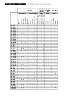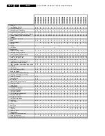
List of PWBs, Features, Technical specifications
GB 9
VR120
1.
1.3
Technical specification
Mains voltage
: 220 - 240 V, +/- 10%
Mains frequency
: 45 - 65 Hz
Power consumption
: mono 12.5 W during
operation
: HiFi 16 W during
operation
without Low Power Standby
: mono 4 W during
standby
: HiFi 4.4 W during
standby
with Low Power Standby
: < 4 W standby
Ambient temperature
: +10°C to +35°C
Relative humidity
: 20 - 80 %
Dimensions
: 380 x 260 x 94 mm
Weight
: 3,7 kg
Fast forward/rewind time (turbo)
: typ. 100s (E180
cass.)
Position of use
: horizontally, max.
15°
Video resolution
:
≥
240 lines
Audio SP: Linear Audio
: 80Hz - 10kHz (
±
6
dB)
Audio LP: Linear Audio
: 80Hz - 5kHz (
±
6
dB)
Stereo FM Audio
: 20Hz - 20kHz
(
±
3dB)
Euroconnector (AV1) SCART plug 1
Connection to TV, monitor, projection TV ...
Pin 1
ARO (audio right out) 500 mV
rms
+/- 3 dB R
out
1 kOhm
Pin 2
ARI (audio right in)
0,2 V
rms
to 2V
rms
R
in
10 kOhm
Pin 3
ALO (audio left out)
500 mV
rms
+/- 3 dB R
out
1 kOhm
Pin 6
ALI (audio left in)
0,2 V
rms
to 2 V
rms
R
in
10 kOhm
Pin 7
Blue (out) **)
Pin 8
Switching output:
(with R
load
= 10kOhm, C
load
<2nF)
low: 2 V
high: 9.5 V
rise time: 5 ms
Pin 11 Green (out) **)
Pin 15 Red (out) **)
Pin 16 Blanking (out) **)
loop through enabled during
standby, view-mode
Pin 19 CVBS II (video out)
1 V
pp
+1/-2dB
R
out
75 Ohm
Pin 20 CVBS I (video in)
1 V
pp
+3/-3dB
R
in
75 Ohm
**) passive loop through from AV2
Euroconnector (AV2) SCART plug 2
Connection to decoder, SAT tuner, video disc, 2nd VCR ...
Pin 1
ARO (audio right out) 500 mV
rms
+/- 3 dB R
out
1 kOhm
Pin 2
ARI (audio right in)
0,2 V
rms
to 2V
rms
R
in
10 kOhm
Pin 3
ALO (audio left out)
500 mV
rms
+/- 3 dB R
out
1 kOhm
Pin 6
ALI (audio left in)
0,2 V
rms
to 2 V
rms
R
in
10 kOhm
Pin 7
Blue (out) **)
Pin 8
Switching input only:
low: 2 V (low)
R
in
10 kOhm
high: 4.5 V (high)
R
in
10 kOhm
Pin 11 Green (in) *)
Pin 15 Red (in) *)
Pin 16 Blanking (in) *)
loop through enabled during
standby, view-mode
Pin 19 CVBS II (video out)
1 V
pp
+1/-2dB
R
out
75 Ohm
Pin 20 CVBS I (video in)
1 V
pp
+3/-3dB
R
in
75 Ohm
*) passive loop through to Euroconnector AV1
Cinch Audio/Video input on front panel (OPTION)
Audio:
AINFR (audio right in) red
0.2 V
rms
to 2 V
rms
typ. 500 mV
rms
AINFL (audio left in) white 0.2 V
rms
to 2 V
rms
typ. 500 mV
rms
Input impedance
47 kOhm
Video:
VFR yellow
1 Vpp + 3 / -3 dB
Input impedance
75 Ohm
Cinch Audio Out Rear (OPTION)
AOUT1R (audio right out) red 500 mV
rms
+/- 3 dB R
out
1 kOhm
AOUT1L (audio left out) white
500 mV
rms
+/- 3 dB R
out
1 kOhm
This outputs are in parallel with the corresponding outputs on
Euroconnector 1.
TUMOD
Modulator:
Frequency range loop through
45 MHz - 860 MHz
Gain:
ANT IN - TV OUT
2 dB + 3 / -2 dB
ANT IN - TUN OUT
2 dB + 3 / -2 dB
Switch for RF input attenuation
NO
Frequency range out (tuned by IIC bus)
Ch 21 - Ch55
Tuner:
Frequency range
43 MHz - 860 MHz
for UK
450 MHz - 860MHz
Input voltage
max.
< 100 dB
µ
V
min.
> 60 dB
µ
V
Summary of Contents for VR570
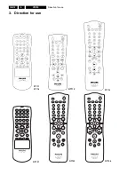
Page 12: ...Direction for use GB 12 VR120 3 3 Direction for use RT111 RT116 RT112 RT114 RT123 RT121 RT128 ...
Page 15: ...Direction for use GB 15 VR120 3 SAT VR870L VR870CC VR720 Set width 435 mm ...
Page 56: ...Service modes Repair tips GB 56 VR120 5 Engineer s remarks ...
Page 79: ...Circuit diagrams and PWB layouts Wiring diagram 79 VR120 7 7 16 Wiring Diagram Motherboard ...
Page 81: ...Circuit diagrams and PWB layouts Wiring diagram 81 VR120 7 Engineer s remarks ...
Page 82: ...82 VR120 7 Circuit diagrams and PWB layouts Wiring diagram Engineer s remarks ...
Page 83: ...Circuit diagrams and PWB layouts Wiring diagram 83 VR120 7 7 18 Mother board component side ...
Page 119: ...Tape deck GB 119 VR120 10 ...
Page 123: ...Tape deck GB 123 VR120 10 Engineer s remarks ...


