Electrical alignments
GB 91
VR120
8.
8.
Electrical alignments
8.1
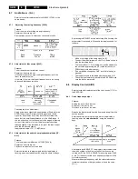
Measuring instruments
The following instruments are required to carry out the
electrical setting work:
1. Dual trace oscilloscope
Voltage range
: 0.001 ~ 50V/Div.
Frequency range
: DC ~ 50 MHz
Probe
: 10:1; 1:1
2. Digital Multimeter
3. Frequency meter
4. Sine-wave generator
: 0 ~ 50MHz
5. Test pattern generator
6. Plastic adjustment tool
7. Isolating transformer (regulating transformer)
8. VHS test cassette 4822 397 30103
SPC test cassette 4822 397 30268
VHS test cassette
8.2
Setting instructions
8.3
Video signal processing (VS-SEC)
Service tasks after replacement of ICs 7004, 7072:
Before commencing adjustment:
Call the service test program and enter Step 10 (Dummy
mode). Remove the drive from the motherboard.
8.3.1
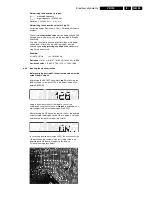
3.3 MHz adjustment [3089] (for SECAM)
Purpose:
To adjust the mixing oscillator
Consequences of incorrect settings:
Cross patterns in coloured areas, coloured noise.
8.3.2
SECAM chrominance record current adjustment [3088]:
Purpose:
To set the optimum record SECAM chroma level.
Symptom, if incorrectly set:
If the record level is too high, beats may appear on the
picture. If the level is too low, the colour may be degraded.
Counter Reading Start
0
0040 ±8
0310 ±12
Video
Blank B&W Pattern
Color Bars
Audio
Blank 6kHz (mono)
40Hz, 3kHz, 15kHz (Mono & Stereo)
The element
to be set
Test point: Connection
point for the measuring
instrument (signal)
Operating mode:
Example:
SP, Record & Play
Record video signal and play
back section just recorded
TP
ADJ.
MODE
INPUT
Emitter
7513
R3045
SP.Record &
Playback
SCART-Input
White picture
TAPE
MEAS. EQ
SPEC.
Blank tape
Oscilloscope,
Video Pattern
Generator
1V
pp
±40mV
Required test signal and
signal input:
Example: White picture
video signal to SCART
input
Measuring
instrument
Required value
Tape required for the
setting work
A: AC, 50mV/Div, 50ns/Div
0V
IC 7072 Pin 17
PB
Summary of Contents for VR570
Page 12: ...Direction for use GB 12 VR120 3 3 Direction for use RT111 RT116 RT112 RT114 RT123 RT121 RT128 ...
Page 15: ...Direction for use GB 15 VR120 3 SAT VR870L VR870CC VR720 Set width 435 mm ...
Page 56: ...Service modes Repair tips GB 56 VR120 5 Engineer s remarks ...
Page 79: ...Circuit diagrams and PWB layouts Wiring diagram 79 VR120 7 7 16 Wiring Diagram Motherboard ...
Page 81: ...Circuit diagrams and PWB layouts Wiring diagram 81 VR120 7 Engineer s remarks ...
Page 82: ...82 VR120 7 Circuit diagrams and PWB layouts Wiring diagram Engineer s remarks ...
Page 83: ...Circuit diagrams and PWB layouts Wiring diagram 83 VR120 7 7 18 Mother board component side ...
Page 119: ...Tape deck GB 119 VR120 10 ...
Page 123: ...Tape deck GB 123 VR120 10 Engineer s remarks ...


